Download
1 / 40
420 likes | 559 Views
Introductory Electronics. Peter Beens peter@beens.org ACSE Conference 2004. What’s Included…. What’s an Electrical Circuit? Invisible Quantities (V, I, R) Safety Basic Components Resistors, Batteries, Light Emitting Diodes (LEDs), ICs, Voltage Regulator Ohm’s & Kirchhoff’s Laws

E N D
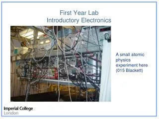
Introductory Electronics Peter Beens peter@beens.org ACSE Conference 2004
What’s Included… • What’s an Electrical Circuit? • Invisible Quantities (V, I, R) • Safety • Basic Components • Resistors, Batteries, Light Emitting Diodes (LEDs), ICs, Voltage Regulator • Ohm’s & Kirchhoff’s Laws • Simple Circuits • Integrating to the Parallel Port (basics only) • Textbook & Web References
What’s an Electrical Circuit? • Every circuit requires these three things: • Power Source • Load • Conductor • Optionally, a circuit may include a “control device” such as a switch
Three Main Invisible Quantities • Voltage, symbol - V, units - Volts • Provides the “push” • Current, symbol - I, units - Amperes (Amps) • Flow of Electrons • Amount of Current is dependent on Voltage and Resistance • Resistance, symbol - R, units - Ohms (S) • Limits the amount of current • Represents the “load” of the circuit
Safe Levels • Voltage: 30 V • Voltages inside a computer do not exceed 12 V, except at the power supply and power switch, which could be at 120 V, depending on computer style.Be careful in these areas! • Current: 5 mA (0.005 Amperes)
Voltage Can Be Provided From… • A battery
Voltage Can Be Provided From… • Parallel (Printer) Port Diagram from http://www.doc.ic.ac.uk/~ih/doc/par/
Voltage Can Be Provided From… • Computer Power Supply • Red: 5V • Yellow: 12V • Black: Ground
Voltage Can Be Provided From… • Breadboard (trainer)
Current • …is simply the flow of electrons • Direction depends on convention • Electron flow is from (-) to (+) (flow of electrons) • Conventional flow is from (+) to (-) (hole flow)
Resistors – Basic Specs • Can be rated by… • Resistance (Ohms, S) • Tolerance (% of nominal value) • Power Rating (Watts) • Schematic Symbol…
Resistors – Types • Fixed • Variable (Potentiometer, Rheostat)
Resistors – Colour Code Reproduced by permission of Tony van Roon, 2002http://www.uoguelph.ca/~antoon
Resistors – Colour Code Javascript Resistance Calculator available at http://www.beens.org/misc/resCalc/resistor.htm
Resistors – Colour Code Example • 1st band: orange = 3 • 2nd band: orange = 3 • 3rd band: red = 2 (i.e. 102) • 4th band: gold = 5% 33 x 102 = 3300 S = 3.3 kS
Ohm’s Law “Current (I) is proportional to Voltage (V) and inversely proportional to Resistance (R)”
Ohm’s Law and Power Formulas Reproduced by permission of Tony van Roon, 2002http://www.uoguelph.ca/~antoon
Kirchhoff’s Voltage Law • Used in series circuits • “The sum of the voltage drops equals the applied voltage”, or… • “The sum of the voltage drops around a closed loop equals zero”
Kirchhoff’s Voltage Law (2) Parallel Port
Kirchhoff’s Current Law • “The current entering a junction must equal the current leaving the junction” • Use in parallel circuits.
Series Circuits • One current path, therefore the current is the same everywhere • Total resistance is the sum of the individual resistances
Parallel Circuits • More than one current path • Total current is the sum of the individual currents
Light Emitting Diodes • A type of diode designed toemit light • Can be visible or IR • 2 V voltage drop • Typically draws 20 mA (0.020 A) • Schematic Symbol…
Protecting the Parallel Port • Use a 74LS245 “Octal Bus Transceiver” to protect the computer parallel port
2N3904 TIP31 Interfacing a Motor to the Parallel Port (A stepper motor would require more outputs)
Integrated Circuits • 7400 series typically used for logic gate experiments • Very susceptible to voltage variations and static discharge • Note pin 1 on diagram • Refer to applicable data-sheet for pinouts
7805 Voltage Regulator • Part of the 78xx series of voltage regulators • Can be used to convert 9 V to 5 V for digital circuits Reproduced with permission; see http://ohmslaw.com/Steps.htm
Textbook References • Computer Engineering: An Activity-Based Approach (Holt) • Networks, Interfaces and Integrated Circuits (Holt) • Essentials of Electronics (Petruzella)
Web References • Learn Electronics Tutorials and Information Pageshttp://www.twysted-pair.com/ • Electronics Tutorials • http://www.electronics-tutorials.com/ • Tutorials for Learning about Electronics • http://www.iguanalabs.com/maintut.htm • DC/AC & Digital Electronics • http://www.sweethaven.com/studyaids.asp
Web References (2) • Jones on Stepper Motors • http://www.cs.uiowa.edu/~jones/step/ • Holt Software • http://www.holtsoft.com/ • Turing, Computer Engineering textbooks • Tony’s Website • http://www.uoguelph.ca/~antoon/ • Many excellent tutorials, example circuits
Web References (3) • Introductory Electronics Website Reviews (Beens.org) • http://www.beens.org/websiteReviews/introElectronicsWebsiteReviews.htm
Credits • Parallel Pinout Diagram • Ian Harries <ih@doc.ic.ac.uk> • http://www.doc.ic.ac.uk/~ih/doc/par/ • Used with permission • Trainer Picture • classic@classictech.on.ca (London, ON) • http://www.classictech.on.ca/ • Used with permission • Resistor Power Ratings Diagram • Quality RF Services, Inc. • http://www.qrf.com/
Credits • Holt Software Pictures • http://www.holtsoft.com/ • Used with permission • Ohm’s Law & Colour Code Pictures • http://www.uoguelph.ca/~antoon/ • Used with permission • 7805 with 9V Battery Diagram • “Floppy the Robot” • http://ohmslaw.com/Steps.htm • Used with permission
Contact Info… • Pete BeensNiagara Falls • Web: http://www.beens.org • Email: peter@beens.org Contact me or check www.acse.net/resources.htm for resources Be sure to join our mail list! www.acse.net/email.htm