Download
1 / 32
320 likes | 469 Views
Dynamical plasma response during driven magnetic reconnection in the laboratory. Ambrogio Fasoli * Jan Egedal MIT Physics D pt & Plasma Science and Fusion Center Ackn.: W.Fox, J.Nazemi, M.Porkolab *Now at EPFL Physics D pt & Centre de Recherche en Physique des Plasmas.

E N D
Dynamical plasma response during driven magnetic reconnection in the laboratory Ambrogio Fasoli* Jan Egedal MIT Physics Dpt & Plasma Science and Fusion Center Ackn.: W.Fox, J.Nazemi, M.Porkolab *Now at EPFL Physics Dpt &Centre de Recherche en Physique des Plasmas
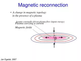
Our definition of magnetic reconnection • Change of magnetic field topology in the presence of plasma • Reconnection rate: value of E-field along X-line, perpendicular to plane over which flux annihilates
Outline • Driven reconnection in the VTF open cusp • Conditions to create a current channel • Dynamical evolution of j and E • j||and dE/dt linked through ionpolarization current • Size of diffusion region (EB0) • Orbit effects • Future work on VTF • New diagnostics • Closed cusp configuration
Magnetic Reconnection on VTF The VTF device 2 m • Origin of fast time scale for reconnection, mechanisms behind breaking of frozen-in flux • Particle orbits ? • Instabilities / waves ? • ….
Diagnostic ‘workhorses’ on VTF 45 heads L-probe 40 Channels B-probe
Ex. of target plasma profiles Bcusp = 50mT, Bguide= 87mT; PECRH ~ 30 kW VTF configuration • lmfp>>L, tcoll>torbit,tA;ri<<L • S = m0LvA/h>>1 • Plasma production by ECRH separate from reconnection drive J.Egedal, A.Fasoli et al., RSI 71, 3351 (2000)
Reconnection drive • Ohmic coils driven by LC resonant circuit • Flux swing ~ 0.2 V-s, duration ~ 6 ms (>>treconnection) • Vloop ~ 100 V, vExB ~ 2km/s ~ vA/10
Sketch of poloidal flux during reconnection drive No reconnection as in ideal MHD Fast reconnection as in vacuum
Plasma response to driven reconnection(3) • Current layers develop for l0=Bguide/Bcusp~3m • No steady-state • Questions: • How much max current / min anomalous resistivity (though ratio E/J is not constant!)? • What determines the size and time evolution of the diffusion region where ideal MHD breaks?
Ipmax [kA] l0=Bguide/Bcusp [m] Anomalous resistivity - Current sustained in plasma determines reconnection rate - For l0=Bguide/Bcusp<3m Ip ~ 0 reconnection rate is same as in vacuum hmeas/hSpitzervs le/l0 First observation of strongly anomalous parallel resistivity (hmeas = Ef/Jfmax)
Ideal region: E + v×B= 0 E · B = 0 - Ez -l0 l0 2x 2y Electrostatic potential(away from the X-line) E= Ezz - B=b0 ( x x – y y + l0 z) =½Ezl0log(|x/y|) E = Ez ( x + y + z)
½Ezl0log(x/y) Experiment Theory Ez 0 Poloidal Drift w/o e.s. potential: charge separation No charge separation if EtotB =½Ezl0log(x/y) Observation of self-consistent e.s. potential J.Egedal and A.Fasoli, PRL 86, 5047 (2001) Deviations from EB=0 are observed close to separatrix diffusion region
The size of the diffusion region(1) Experimental measurement Frozen in law is broken where EB0 EB=(E -) B Fit extending form valid in ideal region d = 3.5 cm
Neon Nitrogen Krypton Xenon The size of the diffusion region(2) • The size of thediffusion region is clearly independent of ionmass and ne • It cannot be related to c/wpi,e or ri,s
The size depends • on [cm] The size of the diffusion region(3)
Temporal evolution of the current channel Time in steps of 12 ms Time response of the toroidal current H2 f ~20-30 kHz Ar
In phase withVloop 900 ahead of Vloop 0 – 1.2 kA/(Vm2) 0 – 20 mAs/(Vm2) Plasma response to an oscillating drive(2) • The current profile • can be separated in • two parts: What causes the out of phase current?
Ion polarization currents due to d/dt Ion polarization current: Quasi neutrality: fits exp. Data with = 3.5 cm
Interpretation with polarisation current predicts time evolution and shape of current channel MEASURED change in f and j dt between t=0 and 30ms THEORY / FIT
, ; Circuit model for VTF plasmas(1)
Deviation? As the observed dependence implies Cj2Vloop Cj2Vloop [As] [As] Circuit model for VTF plasmas(2) • Total current is measured in each • shot by a Rogowsky coil • Values of R j1 and Cj2 obtained • by curve fitting
Would give c/wpe too small (<103) & can’t explain phase far too small with strong guide field, would give c/wpi Only off-diagonal terms (toroidal symmetry) What breaks the frozen in condition? The plasma frozen in condition is violated where: Generalized Ohms law:
[cm] Breaking the frozen in law • All electrons are trapped • limiting macroscopic current channel • Electrons short circuit electric • fields along their orbits • The frozen in law is broken in areas • where the orbits do not follow the • field lines: E•B0 Orbit width, cusp= (g l0)0.5 J.Egedal, PoP 9, 1095 (2002)
Conclusions • Fast, collisionless driven reconnection directly observed • Bguide <~ Bcusp • No current channel, trapped orbits; self-consistent plasma potential • Bguide>>Bcusp • Dynamic evolution of current profile and self-consistent potential • Classical collisions: not important • Ion polarisation current (analogy with RLC circuit) explains observed reconnection dynamics • Key parameter is • Diffusion region does not scale with el./ion Larmor radius, el./ion skin depth, but with characteristic particle orbit size • Direct measurements of different terms in generalised Ohm’s law suggest that pe (off-diagonal) and/or dJ/dtterms are needed (kinetic effect)
Future developments • Energy and velocity distributions • Laser Induced Fluorescence • fi(v) at one position; planar LIF fi(v, x) with intensified CCD • E.s. energy analyzer • Systematic analysis of e.s. and e.m. fluctuations • Spatial and temporal correlations; effect on plasma effective resistivity • Combined reconstruction of Y(x,t) and fe,i(v,x) around X-point particle energization mechanism • Machine upgrades • Increase strength of reconnection drive (reduce ECRH frequency) • Installation of in-vessel coils • Reduction in direct plasma losses: from collisionless to collisional regime
VTF Diagnostics: LIFE.g. planar set-up: fi(vklaser,x,y) • Pulsed dye laser (Lambda Physik Scanmate pumped by Nd:Yag) pumps 611.5 nm line Elaser ~ 20 mJ in 10 ns • LIF detected at 461 nm (intensified CCD?) 2 1 3
PMT IF Present set-up for LIF on VTF laser beam
First observation of LIF on VTF ArII plasma Broad band, Elaser ~ 5 mJ/pulse, Dtlaser~ 15 ns
Plasma edge time (10-5 s) 250 250 Freq (MHz) Freq (MHz) Increased turbulence close to current channel, where gradients are large f < 100 MHz << fpe 0 0 E.S. fluctuations during reconnection, weak Ip J(r) vs .time