Download
1 / 21
210 likes | 345 Views
Ion energization during magnetic reconnection in MST RFP. D.J. Den Hartog, R . M. Magee , S .T.A. Kumar, V.V. Mirnov ( University of Wisconsin–Madison ) D. Craig ( Wheaton College ) G. Fiksel ( Laboratory for Laser Energetics ) J.B. Titus ( Florida A&M University ).

E N D
Ion energization during magnetic reconnection in MST RFP D.J. Den Hartog, R. M. Magee, S.T.A. Kumar, V.V. Mirnov (University of Wisconsin–Madison) D. Craig (Wheaton College) G. Fiksel (Laboratory for Laser Energetics) J.B. Titus (Florida A&M University) MMFW Madison, Wisconsin 6 May 2011
Ions are heated impulsively during magnetic reconnection. • Energy is transferred from the equilibrium magnetic field to ion thermal energy. • Heating time (100 μs) is much faster than i-e collision time (10 ms). • Power flow from equilibrium magnetic field is larger than Ohmic input power. • Pmag~ 10 kJ/ 100s = 100 MW • Pohmic~ 5 MW
Outline • Magnetic reconnection in MST • Majority ion energy distribution • Neutron flux measurements • Neutral particle energy spectra • Impurity ion temperature • CHERS measurements of local C+6Tperp and Tpar Small population of fast ions generated during reconnection Anisotropy with Tperp> Tpar during heating
The Madison Symmetric Torus is a large, moderate current reversed field pinch. R = 1.5 mIp~ 400 kA ne = 0.4 - 2.0 x 10¹⁹ m-3 a = 0.52 m B = 0.5 T Ti,e= 0.2 - 2 keV
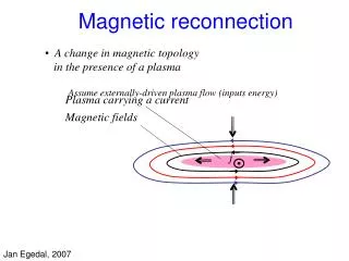
Magnetic reconnection in MST is impulsive and periodic. • Reconnection events are characterized by a burst of resistive tearing mode activity.
Much is known about ion heating in MST. • Equilibrium magnetic field is the ultimate energy source. • The heating rate is very large (3-10 MeV/s). • The majority ion heating efficiency ~ m1/2. • Fully-developed magnetic turbulence is required (i.e. m=0 is a necessary condition). • Impurities tend to be hotter than the majority ions. However, a comprehensive theoretical model of the heating mechanism remains elusive.
Neutron flux measurements provide information about ion energies. • D-D fusion reaction produces neutrons, • Neutron emission rate is a function of ion energy and density, • A small number of fast ions can produce as many neutrons as a thermal plasma.
Neutron flux measurements do not agree with predictions using Maxwellian assumption. • Measured neutron flux is much larger than expected for thermal ions
Information about fi can be obtained from neutral flux measurements. • The neutral flux is related to fi(v,x)by electrostatic energy analyzer • Attenuation (α) and neutral density profile (na) are known, so information about fican be extracted. electron multiplier D+ He stripping cell D0
Derived ion energy spectrum reveals a significant tail in ion distribution function. after reconnection • fi(E) is well-modeled by • fi(E)= A exp(-E/T) + B E-γ before reconnection • Spectral index • varies with density • decreases rapidly during reconnection events
E|| induced during reconnection can accelerate ions to high energies. • Characteristics: • core amplitude ~ 50 V/m • duration ~ 100 μs • extends across minor radius to suppress current in the core and drive current in the edge • Ion acceleration from parallel electric field has been used elsewhere (MAST, ZETA) to explain suprathermal ion population. • Plausible scenario for MST. (Courtesy of W. Ding.)
Ions bouncing off of moving magnetic mirrors can gain energy (Fermi acceleration). • First proposed by Fermi (1949) to explain high energy cosmic rays. • Applied to Earth’s magnetosphere to explain high energy electrons (Drake, 2006). • Predicts beta dependent power law energy distribution (γ = 3.7 for β=0.16).
CHERS can measure both Tperp and Tpar locally. • CHargeExchange Recombination Spectroscopy measures C+6 impurity ion temperature. (Courtesy of S. Oliva.)
Impurity ion temperature anisotropy is observed during reconnection heating. • Tperp > Tpar during heating implies perpendicular heating mechanism. • ΔTpar decreases with density, ΔTperp does not. • Anisotropy increases with density, contrary to expectation from collisionalisotropization.
Energy flows through multiple channels. energy energy Tperp,C Tperp,D Tpar,D Tpar,C Cranmer et. al.Astrophys. J. 518, (1999)
Inverse density dependence of ΔTpar reproduced by model with varying Zeff • Known impurities (C, B, O, N, Al) included in proportion to give: • Zeff= 4.2 in low density Zeff= 2.0 in high density
Summary • High energy tail appears in majority ion distribution function. • Generated at reconnection. • Well-described by power law. • A few percent of total density, with energy ~ 1 - 5+ keV. • Ion runaway and Fermi acceleration are possible mechanisms. • Impurity ion anisotropy appears during heating with Tperp>Tpar. • Implies perpendicular heating mechanism (ICRH or stochastic heating). • Density dependence of anisotropy may be due to changing relative impurity content.