Download
1 / 42
440 likes | 661 Views
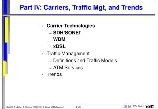
Part IV: Carriers, Traffic Mgt, and Trends. Carrier Technologies SDH/SONET WDM xDSL Traffic Management Definitions and Traffic Models ATM Services Trends. Synchronous Digital Hierarchy – SDH. SONET: Synchronous Optical Network. ANSI-SONET (U.S.A.) and ETSI-SONET (Europe).

E N D
Part IV: Carriers, Traffic Mgt, and Trends • Carrier Technologies • SDH/SONET • WDM • xDSL • Traffic Management • Definitions and Traffic Models • ATM Services • Trends
Synchronous Digital Hierarchy – SDH • SONET: Synchronous Optical Network. • ANSI-SONET (U.S.A.) and ETSI-SONET (Europe). • SDH: Synchronous Digital Hierarchy (international): • Synchronous frames: 125 s • Integration of ATM-and STM-baseddata. • Compatibility withexisting equipmentand signaling. • Support of varioustransmission rates. Transmission Rate in Mbit/s User Data Rate in Mbit/s SONET SDH STS-1 STS-3 STS-9 STS-12 STS-24 STS-36 STS-48 STS-192 STM-1 STM-3 STM-4 STM-8 STM12 STM-16 STM-64 51,84 155,52 466,56 622,08 1244,16 1866,24 2488,32 9953.28 50,12 150,336 451,008 601,344 1202,688 1804,032 2405,376 9621.504 STS-x: Synchronous Transfer Signal level x STM-y: Synchronous Transport Modul level y
SONET – Architecture • Section: Fiber-optical cable between sender/receiver. • Line: Sequence of sections. • Unchanged internal signal and channel structure. • Path: Interconnection of two devices. Path Terminals Terminals Line Line Section Section Section Section SONET Multiplexer (PTE + LTE) Add-Drop Multiplexer (LTE) SONET Multiplexer (PTE + LTE) Repeater (STE) Repeater (STE)
SONET – Frame (STS-1) • The frame length is 125 s. • Rows and columns are used. • Transmission from left to right by rows. • Frames contain user data and additional control data as well as timing information. STS - Frame: (3+6) * (3+87) Octett 810 Octett Brutto data: 810 Octett / 125 s 51,84 Mbit/s User data: 810 - [3*(3+6) + 1*(3+6)] Octett 49,536 Mbit/s Transport overhead (3 columns) Synchronous Payload Environment (87-1 columns) 0 s Section overhead (3 rows) Line overhead (6 rows) 125 s Path overhead (1 column)
SONET – Frame (STS-N) • Basic frame: STS-1 with 810 octets. • Higher rate SONET channels formed by octet-interleaving of multiple STS-1 inputs: • STS-N rate is formed from N STS-1 inputs. • Advantage: STS-1 line cards remain operable in an STS-1-to-STS-N multiplexor. • STS-N frame: 90 * N columns per row, including 4 * N columns of interface overhead. • Example: STS-3 = STM-1 (155.52 Mbit/s) Transport overhead (3*3 columns) Synchronous Payload Environment ((87-1) * 3 columns) 0 s Section overhead (3 rows) Overhead 5.184 Mbit/s Payload 150.336 Mbit/s Line overhead (6 rows) Path overhead (1*3 columns) 125 s
SONET – Localization of Payload • Pointer H1 and H2 contain values for number of payload bytes inbetween H3 and J1. Direct access to single channels. No (de-)multiplexing necessary. • Payload may be located in two STS-1 frames. Frame N (9 rows) H2 H1 (9 rows) Frame N+1 (9 rows) H2 H1 Path overhead (1 column) H3 is used as padding byte.
Point-to-PointTerminal Point-to-PointTerminal Point-to-PointTerminal Add/Drop Multiplexer Point-to-PointTerminal SDH Network Topologies Point-to-point configuration with 1:4 protection channel sharing Linear Add/Drop Route
Fiber Optic Networks Revisited Traditional use of fibers: Optical Fiber Laser Receiver • Current transmission capacities: • 2.5 Gbit/s (OC-48) • 10 Gbit/s (OC-192) • Lasers available for 850 nm, 1310 nm and 1550 nm wavelength.
Wavelength-Division Multiplexing Dense* Wavelength-Division Multiplexing (DWDM): Optical Fiber Array of Photodetectors Array of Lasers l1l2l3l4 • Current available transmission capacities: • 96 lasers at 2.5 Gbit/s = 240 Gbit/s (OC-4608) • 32 lasers at 10 Gbit/s = 320 Gbit/s (OC-6144) • Soon 128 lasers at 10 Gbit/s > 1 Tbit/s (=1.000.000.000.000 bits/s) * „Dense“ WDM: More than 10 lasers used simultaneously. Today: WDM usually means dense WDM.
Breaking the Internet Gridlock • Utilizing publically available infrastructure: • How to serve private users with sufficient bandwidth? • How to interconnect two enterprise sites with an at least medium bandwidth solution? • Solution possibilities: • Hybrid fiber/coax (HFC) technology: any configuration of fiber-optic and coaxial cable that is used to distribute local broadband communications: • Shared downstream bandwidth, up to 30 Mbit/s. • Wireless cable. • xDSL (Digital Subscriber Lines). • Deployment: 650 M customers on twisted pair.
ADSL Technology – Overview (1) • Twisted pair access to the information highway: • Delivering video und multimedia data. • Avoids the replacement of existing cabling. • Transformation of existing telephone network into a multi-service network by applying modulation. • Use of full copper frequency spectrum (app. 1.1 MHz). 144 kbit/s (POTS) Server 16 … 640 kbit/s *) Existing Copper ADSL Modem ADSL Modem Core Network Internet 1.5 … 9 Mbit/s *) depending on the implementation architecture
ADSL Technology – Overview (2) • ADSL Forum Reference Model: Vc Va UC-2 U-C U-R U-R2 T-SM T-P T Digital Broadcast T.E. ATU-C Broadband Network ATU-R ATM-SM ATU-C Splitter Splitter Narrowband Network POTS-C POTS-R Network Management ATU-C Access Node Premises Distribution Network PSTN Phonesets
DSL Comparison DSL Scheme Downstream [kbit/s] Upstream [kbit/s] Voice Support IDSL UDSL SDSL HDSL ADSL VDSL 144 1,000 160 – 1,168 2,048 1,500 – 8,000 1,500 – 25,000 144 300 160 – 1,168 2,048 64 – 800 1,600 Active Splitterless No No Passive Passive ADSL: Asymmetric DSl HDSL: High bit-rate DSL IDSL: ISDN DSL SDSL: Symmetric DSL UDSL: Universal DSL VDSL: Very high bit-rate DSL
Data Rate [Mbit/s] 1.5 or 2 1.5 or 2 6.1 6.1 Wire Gauge [mm] 0.5 (26 AWG) 0.4 (24 AWG) 0.5 (26 AWG) 0.4 (24 AWG) Distance [km] 5.5 4.6 3.7 2.7 Duplex Bearer Channels [kbit/s] C Channels 16 64 Optional 160 Channels 384 544 576 Downstream Bearer Channels [Mbit/s] n*1.536 1.536 3.072 4.608 6.144 n*2.048 2.048 4.096 ADSL Technology – Capabilities • Data rates depend on: • Length of copper line, • Wire gauge, • Presence of bridged taps, and • Cross-coupled interference. • 95% of todays loop plantsmeet these measures. • Requires advanced digitalsignal processing and advanced coding schemes to deal with varying noise figures.
ADSL Technology – DMT Modulation • To work simultaneously withPOTS on copper line. • Lower 4 kHz are used by POTS. • Discrete Multi Tone (DMT):256 separate sub-frequenciesfrom 64 kHz. • Amplifica-tion varies dependenton frequency. Discrete Multitone (DMT) Modulation POTS each 4 kHz (32 QAM) 1.4 MHz Data rate = No of channels * no of bits/channel * modulation rate Theoretical max upstream: 25*25*4k = 1.5 Mbit/s Theoretical max downstream: 249*15*4k = 14.9 Mbit/s
ADSL Network Architectures (1) • ADSL-ATM network architecture, point-to-point: DSLAM: Digital Subscriber Line Access Multiplexor
ADSL Network Architectures (2) • ADSL-ATM including L2TP: LAC: Local Access Carrier LAC: Local Access Carrier
Part IV: Carriers, Traffic Mgt, and Trends • Carrier Technologies • SDH/SONET • WDM • xDSL • Traffic Management • Definitions and Traffic Models • ATM Services • Trends
Traffic Engineering Definition • Traffic Engineering is the task of mapping traffic flows onto an existing physical topology. • The goalsof traffic engineering are: • Minimization of packet loss and packet delay. • Optimization of network resources (avoiding overload situations through load balancing). • Traffic engineering “applications” allow for a precise control of how traffic flows are placed within a routing domain.
Policies and Mechanisms • Traffic engineering consists of: • Traffic management (short-term) and • Network planning (long-term). • Traffic management: • Set of policies and mechanisms for satisfying a range of diverse application service requests. • Acting across: diversity and efficiency. • Subsumes traditional ideas of congestion control: • An overloaded resource suffers from service degradation. • Policies scale back demand or restrict access.
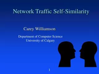
Traffic Models • Goal of effectively managing traffic requires: • Requirements of individual applications and organizations. • Their typical „behavior“. • Traffic Models: • Summarize „expected behavior“. • Obtained by detailed traffic measurements or amenable to mathematical analysis. • State of the art in traffic modelling: • Telephone traffic model and • Internet traffic model. • Change of applications make these models to change!
10 20 30 t 0.01 0.0001 0.000001 Heavy-tailed P(T>t) Exponential Telephone Traffic Model • Call arrival model: • How are calls placed? • Interarrival times drawn from an exponential distribution (poisson process models all arrivals). • Memoryless (certain time elapse does not tell the future). • Call holding-time model: • Call holding-times drawn from an exponential distribution: • Call longer than x decreases exponentially with x. • Heavy-tailed distribution in recent studies:
Internet Traffic Model • Parameters to characterize applications: • Distributions of interarrival times between app. invocations. • Duration of a connection. • Number of bytes transferred during a connection. • Interarrival times of packets within a connection. • Note: There is little consensus on models! • E.g., interarrival times: Exponential or Weibull. • Effective means: Measurements to fit to statistical model. • LAN traffic differs heavily from WAN traffic. • More local bandwidth, tendency for longer holding times, higher peak data rates. • Expensive wide area bandwidth, less volume.
Time Scales of Traffic Management Time Scale Mechanism Net Endsystem Scheduling, buffer management Regulation, policing Routing (connection less) Error detection and correction Feedback flow-control Retransmission Renegotiation Signalling Admission-control Service pricing Routing (connection-oriented) Peak-load pricing Capacity Planning Less than one RTT (Cell level) One or more RTTs (Burst level) Session (Call level) Day Weeks and more
Service Categories • ATM offers six service categories: • Real-time services using resource reservation. • Non-real-time services without resource reservation. • Non-real-time services with partial resource reservation. • Sources have to comply to a previously negotiated traffic characteristic (traffic contract). • Conforming traffic is transported with the negotiated quality of service guarantees.
Real-Time Services (1) • CBR (Constant Bit Rate): • Traffic: constant, Peak Cell Rate (PCR). • QoS parameter: max. Cell Transfer Delay (maxCTD), Cell Delay Variation (CDV), Cell Loss Ratio (CLR). • Example: uncompressed video/audio data. Peak Cell Rate defines a temporal distance: T = 1/PCR. Cells have to be evenly spaced in time. marked or dropped T T T T
Real-Time Services (2) • rt-VBR (Real-Time Variable Bit Rate): • Traffic: Peak Cell Rate (PCR), Sustainable Cell Rate (SCR), Maximum Burst Size (MBS). • QoS parameter: maxCTD, CDV, CLR. • Example: compressed video / audio data T = 1/PCRTS = 1/SCR t T with mean value TS marked or dropped t t t t
Non-Real-Time Services (2) • ABR (Available Bit Rate): • Traffic: Peak Cell Rate (PCR) and Minimum Cell Rate (MCR), flow control mechanism mandatory. • "QoS parameter": minimum cell loss. • Flow control mechanism determines theAllowed Cell Rate (ACR). Link Rate PCR (Peak Cell Rate) dynamic ACR (Allowed Cell Rate) Dynamically changedby the flow control. MCR (Minimum Cell Rate), may be 0. reserved
Usage Parameter Control • Test, whether a cell stream conforms to a given traffic characteristics. • Generic Cell Rate Algorithm: GCRA(T, ). • Virtual Scheduling Algorithm or • Continuous-State Leaky Bucket. • Input parameters: T = 1/PCR, = CDVT. T T T OK OK OK OK Not OK
Public ATM Private ATM Peak Cell Rate Conformance • For CBR traffic, it is sufficient to test peak cell rate. • Usage Parameter Control takes places at the network interfaces. GCRA(T,0) GCRA(T, ) GCRA(T, *) Shaping Sha- ping Physical UPC UPC Private UNI Public UNI
Part IV: Carriers, Traffic Mgt, and Trends • Carrier Technologies • SDH/SONET • WDM • xDSL • Traffic Management • Definitions and Traffic Models • ATM Services • IP Services • Trends
Use of Network Protocols IP is the only protocol that matters anymore! Source: Gartner Group
Data POTS DATA Data Traffic is Overtaking Voice Data Volume Voice Source: CIENA Corp. Time Today POTS Voice-Centric Data-Centric
Effect on (Carrier) Networks • Everything will be data, soon. • The only protocol that matters is IP. • Networks have to accomodate for the exponential traffic growth. • It makes sense to design networks for IP only!
Technology Trends • Chip performance doubles every 18 months (Moore‘s Law). • Modern chips can switch packets as fast as ATM cells. • New router architectures have appeared: • Routing at Gigabit/s speed • Routers support traffic management with thousands of queues per interface • Routers interface directly to DWDM
Layer upon Layer... IP ATM IP IP Sonet ATM Sonet IP DWDM DWDM DWDM DWDM
Traffic Multiplexing in the Backbone IP ATM N x OC-48 DWDMADM SonetADM Sonet OC-48 OC-48 OC-48 DWDM DWDM Ring • Multiplexing of IP traffic over ATM or Sonet no longer required. • Segmentation of IP packets into ATM cells not possible at OC-48.
IP DWDM Optical Internet Backbones (1) N x OC-48 DWDMADM OC-48 DWDM Ring • Most important objective: high bandwidth. • No „Quality of Service“, but „Classes of Service“ • IP-centric Control (no SONET, no ATM). • Traffic engineering using MPLS.
Optical Internet Backbones (2) Optical Crossconnects IP routers Router network Optical network • Optical network: Provides point-to-point connectivity between routers („lightpaths“). • „Lightpaths“ have fixed bandwidth (e.g. OC-48). • „Lightpaths“ define virtual topology, which may be static by design.
Conclusions • Transporting data using IP will be the key task of the „New Public Network“. • IP over ATM can not keep up with the very high-speed backbones (SAR!). • IP over DWDM or IP over Sonet needs to solve the traffic engineering problem. • IP over ATM will remain for small ISPs or large enterprise networks due to its proven reliability and traffic management capabilities.
References (1) • M.-C. Chow: Understanding SONET/SDH; 1995, Andan Publisher, Holmdel, New Jersey, U.S.A.,ISBN 0–9650448–2–3. • The Sonet Home Page; URL: http://www.sonet.com, 1999. • CIENA Inc.: Fundamentals of DWDM; URL: http://www.ciena.com, 1999. • D. Ginsburg: Implementing ADSL; Addison-Wesley, Reading, Massachusetts, U.S.A., July, 1999,ISBN 0-201-65760-0. • M. de Prycker: “Asynchronous Transfer Mode – Solution for Broadband ISDN”, 3rd Edition, 1995, Prentice Hall, Englewood Cliffs, New Jersey, U.S.A., ISBN 0–13–342171–6.
References (2) • X. Xiao, L. M. Ni: Internet QoS: A Big Picture; IEEE Network Magazine, Vol. 13, March/April 1999, pp 8 – 18. • C. Schmidt, M. Zitterbart: Reservierung von Netzwerkres-sourcen – Ein Überblick über Protokolle und Mechanismen; Praxis der Informationsverarbeitung und Kommunikation, Vol. 18, No. 3, 1995, pp 140 – 147. • L. Zhang, S. Deering, D. Estrin, S. Shenker, D. Zappala: RSVP: A New Resource ReSerVation Protocol; IEEE Network, Vol. 7, No. 5, September 1993, pp 8 – 18. • The SWITCHlan backbone network; available at the URL: http://www.switch.ch/lan, 1999. • C. Metz: IP Routers: New Tool for Gigabit Networking; IEEE Internet Computing; November/December 1998, pp. 14-18.