The Efficient Denoising Artificial Light Interference using Discrete Wavelet Transform with Application to Indoor Optic
220 likes | 442 Views
The Efficient Denoising Artificial Light Interference using Discrete Wavelet Transform with Application to Indoor Optical Wireless System . S. Rajbhandari , Prof. Z. Ghassemlooy, Prof. M. Angelova School of Computing, Engineering & Information Sciences,

The Efficient Denoising Artificial Light Interference using Discrete Wavelet Transform with Application to Indoor Optic
E N D
Presentation Transcript
The Efficient Denoising Artificial Light Interference using Discrete Wavelet Transform with Application to Indoor Optical Wireless System S. Rajbhandari, Prof. Z. Ghassemlooy, Prof. M. Angelova School of Computing, Engineering & Information Sciences, University of Northumbria, Newcastle upon Tyne, UK. sujan.rajbhandari@unn.ac.uk http://soe.unn.ac.uk/ocr
Content • Introduction to indoor optical wireless system (OWS) • Challenges in OWS. • Artificial light interference, its effect in indoor OWS links and techniques to mitigate. • DWT based denoising. • Realization of the propose system. • Future works • Conclusion
History of Optical Communication • The very first form of wireless speech communication was achieved at optical wavelengths in 1878 by Alexander Graham Bell, more than 25 years before Reginald Fessenden did the same thing with radio1. Diagram of photophone from Bell paper 1 • Development of LASER in 60’s, optical fibre and semiconductor has made the modern communication possible. • The modern era of indoor wireless optical communications was proposed in 1979 by F.R. Gfeller and U. Bapst2.In fact it was the first LAN proposed using any medium. 1 Alexander Graham BELL, American Journal of Sciences, Third Series, vol. XX, no.118, Oct. 1880, pp. 305- 324. 2 F. R. Gfeller and U. Bapst, Proceedings of the IEEE, vol. 67, pp. 1474- 1486, 1979.
Optical Wireless System (OWS): Overview • Communication system using light beams (visible and infrared) propagated through the atmosphere or space to carry information. • Optical transmitter • Light Emitting Diodes (LED) • Laser Diodes (LD) • Optical receiver • p-i-n Photodiodes. • Avalanche Photodiodes. • Links • Line-of-sight(LOS) • Non-LOS • Hybrid Typical optical wireless system components Optical wireless connectivity 1 1 M. Kavehrad, Scientific American Magazine, July 2007, pp. 82-87.
What OWS offers • Abundance bandwidth High data rate • License free operation • High Directivity small cell size can support multiple devices within a room • Free from electromagnetic interference suitable for hospital and library environment. • cannot penetrate opaque surface like wall Spatial confinement Secure data transmission • Compatible with optical fibre (last mile bottle neck?) • Low cost of deployment • Quick to deploy • Small size, low cost component and low power consumptions. • Simple transceiver design. • No multipath fading
Common Baseband Digital Modulation Techniques • OOK • Simple to implement • High average power requirement • Suitable for Bit Rate greater than 30Mb/s • Performance detiorates at higher bit rates • PPM • Complex to implement • Lower average power requirement • Higher transmission bandwidth • Requires symbol and slot synchronisation • DPIM • Higher average power requirement compared with PPM • Higher throughput • Built in symbol synchronisation • Performance midway between PPM and OOK. • DH-PIM • The highest symbol throughput • Lower transmission bandwidth than PPM and DPIM • Built in symbol synchronisation • Higher average power requirement compared with PPM and DPIM. • Complex decoder
Artificial Light Interference (ALI) 1.2 Sun Incandescent 1 0.8 1st window IR Normalised power/unit wavelength 0.6 Fluorescent 0.4 x 10 0.2 0 0.7 0.8 0.9 1.0 0.3 0.4 0.5 0.6 1.1 1.2 1.3 1.4 1.5 Wavelength (m) • Dominant noise source at low data rate. • Spectral overlapping of signal and interference produce by fluorescent lamp driven by electronic ballasts • can causeserious performance degradation as the interference amplitude can be much higher than signal amplitude. • The effect of noise is minimised using combination of the optical band pass filter and electrical low pass filter. Pave)amb-light >> Pave)signal (Typically 30 dB with no optical filtering) 2ndwindow IR Optical power spectra of common ambient infrared sources. Spectra have been scaled to have the same maximum value.
Fluorescent Light Interference Model1 • mhigh(t) high frequency component. • mlow(t) low frequency component. Low frequency component Optical power penalty due to FLI High frequency component • A. J. C. Moreira, R. T. Valadas, and A. M. d. O. Duarte, IEE Proceedings -Optoelectronics, vol. 143, pp. 339-346.
ALI-Possible Solutions • Differential receiver1 • Differential optical filtering2 • Electrical high pass filter3,4 • Polarisers 5 • Angle diversity receiver 6,7 • Discrete wavelet transform based denoising8,9 • 1 J. R. Barry, PhD Dissertation, University of California at Berkeley, 1992 • 2 A.J.C Moreira, R. T. Valadas, A. M. De Oliveira Duarte, Optical Free Space Communication Links, IEE Colloquium on , vol., no., pp.5/1-510, 19 Feb 1996. • 3 R. Narasimhan, M. D. Audeh, and J. M. Kahn, IEE Proceedings - Optoelectronics, vol. 143, pp. 347-354, 1996. • 4 A. R. Hayes, Z. Ghassemlooy , N. L. Seed, and R. McLaughlin, IEE Proceedings - Optoelectronics vol. 147, pp. 295-300, 2000. • 5S. Lee, Microwave and Optical Technology Letters, vol. 40, pp. 228-230, 2004. • 6R. T. Valadas, A. M. R. Tavares, and A. M. Duarte, International Journal of Wireless Information Networks, vol. 4, pp. 275-288, 1997 . • 7J. M. Kahn, P. Djahani, A. G. Weisbin, K. T. Beh, A. P. Tang, and R. You, IEEE Communications Magazine, vol. 36, pp. 88-94, 1998. • 8 S. Rajbhandari; Z. Ghassemlooy; and M. Angelova, IJEEE, Vol. 5, no. 2 ,pp102-111. 2009. • 9 S. Rajbhandari; Z. Ghassemlooy; and M. Angelova, Journal of Lightwave Technology, on print.
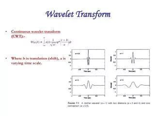
Feature Extraction Tools Time-Frequencies Mapping Wavelet Transform Fourier Transform Short-Time Fourier Transform No time-frequency Localization Fixed time-frequency resolution: Uncertainty problem No resolution problem :Ultimate Transform
Discrete Wavelet Transform 2 2 2 2 (14) Level 1 DWT coefficients Level 2 DWT coefficients Down- sampling Filtering y1h • Coefficient can efficiently be obtained by successive filtering and down sampling. • The two filter are related to each other and are known as a quadrature mirror filter. • Reconstruction is inversion of decomposition process filter, up sample and combine. y2h h[n] Signal h[n] y1l x[n] y2l g[n] g[n]
DWT based Denoising • DWT is a multiresolutional analysis (MRA) tool signals are divided into half-frequency bands at each level of the decomposition. • Separate the received signal into different frequency bands. • Remove the frequency band that corresponding to interference. • Reconstruct the signal using inverse DWT. • Challenge: spectral overlap between the signal and interference (both signals have high PSD at a low frequency region). • The denoising should be carried out to ensure that information lost is minimum. Multiresolutional analysis tree
System Descriptions • FLI is a low frequency band signal, the approximation coefficients need to be manipulated. • For denoising proposes, the approximation coefficients corresponding to the FLI are made equal to zero so that reconstructed signal is free from FLI. • The signal is then reconstructed using the inverse DWT .
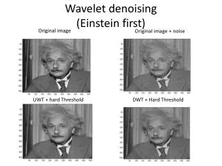
DWT based Denoising • Complete closer of eye in the eye-diagram of the signal corrupted by ALI high BER. • Wide opening of the eye with wavelet denoising. • The number of decomposition level for DWT is calculated using: • where is the ceiling function • Approximate cut-off frequency of 0.5 MHz is used as it provide near optimum performance. Received OOK signal in the presence of the FL interference, • The eye diagram of received signal with wavelet denoising. • The eye-diagram of received signal corrupted by ALI
DWT based Denoising PSD of the OOK with FLI and DWT denoising at 200 Mbps PSD of the OOK with FLI and DWT denoising at 2 Mbps • No significant changes in PSD at frequency > 0.5 MHz. • Significant portion of the spectral content at < 0.3 MHz is removed with no DC contents. • Spectral overlap between signal and interference power penalty.
Performance of OOK with DWT • DWT based receiver reduces the optical power requirement significantly. • Above data rate of 40 Mbps, the optical power penalty for OOK-NRZ is less than 1.5 dB. • Optical power penalty is the highest for OOK due to a high DC content. • Optical power penalty for PPM and DPIM is ~0.5 dB. • Since the PPM has zero spectral component near DC value, PPM offers improved performance. The normalized OPP to achieve a error rate of 10-6 for OOK, 8-PPM and 8-DPIM for ideal and interfering channels and with DWT denoising at data rates of 10 - 200 Mbps.
Implementation- TI DSP DSP Board Using TI DMS320C6713 DSP board + Matlab/Simulink
Conclusion • Indoor optical wireless systems will have a major role in future indoor personal communication. • A number of key challenges needs to be address before fully potential can be realized. • Artificial light interference is a dominant noise source that impair the link performance. • Artificial light interference can be reduced effectively by using the discrete wavelet transform. • Discrete wavelet transform provide improved performance with reduced complexity compared to the high pass filter. • Discrete wavelet transform based denoising can easily be realized using DSP.
Acknowledgement • Northumbria university for providing an studentship. • My supervisors: Prof. Maia Angelova and Prof. Fary Ghassemlooy. • All my colleagues. • Finally my family members.