The Discrete Wavelet Transform
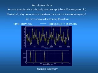
Location of Partial Discharges within a Transformer Winding Using Principal Component Analysis M. S. Abd Rahman, L. Hao, P. L. Lewin University of Southampton, Southampton, UK. PD Source. Introduction.

The Discrete Wavelet Transform
E N D
Presentation Transcript
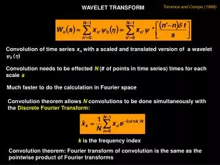
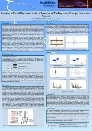
Location of Partial Discharges within a Transformer Winding Using Principal Component AnalysisM. S. Abd Rahman, L. Hao, P. L. Lewin University of Southampton, Southampton, UK PD Source Introduction In order to generate partial discharge inside the transformer winding, a PD source of an artificial void in oil has been developed as shown in figure 3 and its corresponding output signal is shown in figure 4. To simulate PD behavior, a hollow stainless steel sphere was used as the upper electrode. A cylindrical air bubble was trapped inside the sphere of size diameter 4.73mm and length10.30mm. A rectangular perspex block of length 139mm, width 200mm and thickness 7.53mm was inserted between pair of electrodes, the upper electrode was connected to the high voltage supply and the lower was grounded. The whole PD source arrangement was immersed in transformer oil. Partial discharge (PD) is a common phenomena which may occur in high voltage equipment such as power cables and high voltage transformers. It is due to ageing processes, operational over stressing or defects introduced during manufacture. IEC 60270 defines PD as a localised electric discharge that only partially bridges the dielectric insulator between conductors when the electric field exceeds a critical value. PD might occur anywhere inside a transformer particularly along the transformer winding and the discharge signal can propagate along the winding to the bushing and neutral to earth connections. Therefore, the identification of a PD source as well as its location are essential in PD monitoring and evaluation processes. The wavelet decomposition is useful in order to decompose PD signals into detail levels and an approximation by using an approach known as quadrature mirror filtering which splits the signal into two bands, high pass and low pass signals. Wavelets can be used to improve signal to noise ratio in many applications, but in this case it is used to identify the distribution of signal energies in both time and frequency domains. Principal component analysis (PCA) is a pre-processing algorithm that uses an orthogonal transformation to convert a large set of data into set of variables or principal components. In this case, the use of PCA is to compress this data into three dimensions, to aid visualisation. An experiment has been developed in the Tony Davies High Voltage Laboratory that can be used to create PD data over hundreds of cycles of applied voltage in order to investigate the feasibility of using this approach to identify PD locations. Fig. 3. Artificial void in oil PD source Fig. 4. PD signal generated by artificial source Results Signal processing The Discrete Wavelet Transform The discrete wavelet transform is formed by passing the signal through a series of filters. The signal is passed through a low pass filter (m) where the output is the ‘approximation’ coefficients, the signal is also decomposed simultaneously using a high pass filter (n) giving the ‘detail’ coefficients (figure 1). Principal Component Analysis PCA solves an eigenvalue problem. Thus, the data is transformed into a new coordinate system with a corresponding variance. Theoretically, PCA is a linear transformation that projects the set of input data to a new coordinate system, the principal component that has the greatest variance is labelled as the first principal component; the second principal component is the one that has second greatest variance and the third greatest variance becomes the third principal component, allowing projection of the input data into three dimensions as implemented in this case. However, PCA can be two or three dimensionsal depending on the particular application. Approximation coefficients m[k] x[k] a. Bushing tap point b. Neutral end point Fig. 5. 3-D φ-q-n pattern for discharge signal from terminal 8 Detail coefficients n[k] Figure 1: Block diagram of Wavelet single decomposition a. Detail D3 b. Detail D7 Fig. 6. Detail levels at neutral end Experiment The experiment is based on a high voltage transformer winding model BS148:1998 class 1 and a 60 kV transformer bushing, model 60HC755 in order to study the PD activity inside transformer winding. The model contains 2 types of winding, interleaved disc and plain disc winding, in this case PD signal source being injected to the interleaved disc winding whilst the plain disc winding was grounded. The interleaved winding consists of eight terminals, terminal one of the winding is connected to the bushing core bar while the last terminal was grounded. The artificial PD source was injected at each terminal of the winding and the discharge current from the PD source is measured at measurement points. There are two PD measurement points in this case as the PD signal can travel in both directions; the first point is located at the bushing tap and the other is at neutral to earth connection as shown in figure 2. The discharge current flowing to both ends can be measured by using a radio frequency radio transducer (RFCT). The RFCT used in this experiment is the clamp-type split core RFCT EMCO model 93686-5, serial model 9802-50174 which has a measurable frequency range from 10kHz to 200MHz. A digital storage oscilloscope, Tektronix DPO7254 with a bandwidth of 2.5 GHz and sampling rate 40 Gs/s was used to display, analyse and hence store the obtained output signals from both ends. A Mtronix partial discharge MPD 600 and a charge calibrator type cal542 has been used for detecting and recording partial discharge events and charge calibration. a. Bushing tap point b. Neutral end point Fig. 7. Energy distribution Discussion The phase resolved partial discharge plot (φ-q-n) for both the bushing and neutral ends (figure 5) show almost similar PD patterns that are typical of a void in oil PD source. The magnitudes are higher at the neutral end due to the closer location of the PD source along the winding. Wavelet Analysis (typical examples of detail levels for a captured signal are shown in figure 6) can be used as a method to identify the distribution of energies in both the time and frequency domains. Figure 7 shows the analysis of 600 pairs of signals and clearly demonstrates different energy distributions depending on measurement point. Hence this analysis produces a 10 dimensional feature vector for each captured discharge signal. PCA will be used to compress the 10d energy vector into a three dimensional representation. Conclusions RFCT sensors located at both bushing tap and neutral end can detect discharge signals and it is possible to record and store PD signal data over 50 cycles of applied ac voltage. Application of wavelet discrete decomposition is a useful pre-processing technique that can produce a feature vector that represents the distribution of signal energy in both the time and frequency domains. This information can be described in 3 dimensions by using principal component analysis. Further work will consider analysis of the clusters of data produced using this approach to determine whether it provides insight into source location. M.S. Abd Rahman, msar106@ecs.soton.ac.uk University of Southampton, Highfield, Southampton, SO17 1BJ, UK Figure 2: Experiment for simulating partial discharges within a transformer winding. Contact details :