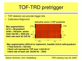
TRD Structure
TRD Structure. module. MCM. 6 planes. TR-detector. 18 channels. chamber. B=0.4T. vertex. max. 16 padrows. 5 module rings. 8 MCM 144 channels. 18 sectors in azimuth. r. . z. 1.2 million channels peak data rate: 16 TB/s ~65000 MCMs computing time: 6 µs.


TRD Structure
E N D
Presentation Transcript
TRD Structure module MCM 6 planes TR-detector 18 channels chamber B=0.4T vertex max. 16 padrows 5 module rings 8 MCM 144 channels 18 sectors in azimuth r z • 1.2 million channels • peak data rate: 16 TB/s • ~65000 MCMs • computing time: 6 µs • MCM performs amplification,digitization, straight line fit,readout network
Data Flow and Data Reduction MCM - Multi Chip Module L1 trigger to CTP TRD PASA ADC Tracklet Preprocessor TPP Tracklet Processor TP Network Interface NI GTU to HLT & DAQ event buffer store raw data until L1A detector 6 layers 1.2 million analog channels charge sensitive preamplifier shaper 10 Bit ADC 10 MSPS 21 channels digital filter preprocess data event buffer fit tracklets for trigger functionality process raw data monitoring builds readout tree for trigger & raw data merge tracklets into tracks for trigger process raw data for HLT time: data / event: peak rate: mean rate: reduction: during first 2 µs (drift time) 33 MB 16 TB/s 257 GB/s 1 after 3.5 µs after 4.1 µs max. 80 KB 600 GB/s - ~ 400 after 6 µs some bytes - - to trigger decision
Multi Chip Module 4 cm PASA Internal ADCs (Kaiserslautern) Digital Frontend and Tracklet Preprocessor Instruction Memory MIMD Processor: 4 CPUs, Global Register File, Interrupt controllers, Counter/Timers, Arbiter for the Global I/O Bus Master State Machine External Pretrigger Serial Interface slave Serial Interface Global I/O-Bus Readout Network Network Interface Quad-ported DMEM
FeeCommunication chain PVSS FED Client FED Server InterCom Layer Config. from file FEE Client Cmd / ACK Channel FeeServer incl. CE FeeServer incl. CE FeeServer incl. CE Service Channel Tested features: •Hardware access via Control Engine •Monitoring of measured values •Adapting deadbands for values •Execution of single and broadcasted commands •Messaging from all layers Acknowledges ... Services Command Broadcast ACK ACK ACK Service Cmd Cmd Cmd . . .
TRAP configuration overview .ASM CODEM ASM_MIMD add r13 c3 r13 shl 1 r11 r11 jmp cc_carry return1 mov bitnum work .DAT .TCS 10 53249 511 127 24 10 53250 11 127 25 10 53251 11 127 26 10 57344 -1895563249 127 10 57345 -1895825408 127 TCC const dut = 3 reset dut write dut, NMOD, 0x1C expect dut, NMOD, 0x1C write NICLK, 1 TRAPs .C + SCSN Master
TRAP internal structure 4 x 4k x 24 1k x 32 256 x 32 r1 r0 IM0 DM DB CPU0 TRAP Arbiter/ SCSN slv Global bus StateM (~25) NI (~12) IRQ(64) Counters(8) Const(20) LUT-nonl(64) Gain corr(42) LUT-pos(128) Fil/Pre(~44) ~280 ~120 r1 r0
Configuring many TRAPs in a chain • Strategy for configuring multiple TRAPs in a chain: • All configuration statements come from the data base. • The common part of the configuration is stored once (identical for all MCMs) plus some individual MCM-specific info. • The command coder creates a config file from DB for each MCM and sends it to InterCom Layer → DCS board → ROB → MCM.