Download
1 / 35
0 likes | 4 Views
To get the complete manual, please open the home page website.<br><br>https://www.aservicemanualpdf.com/

E N D
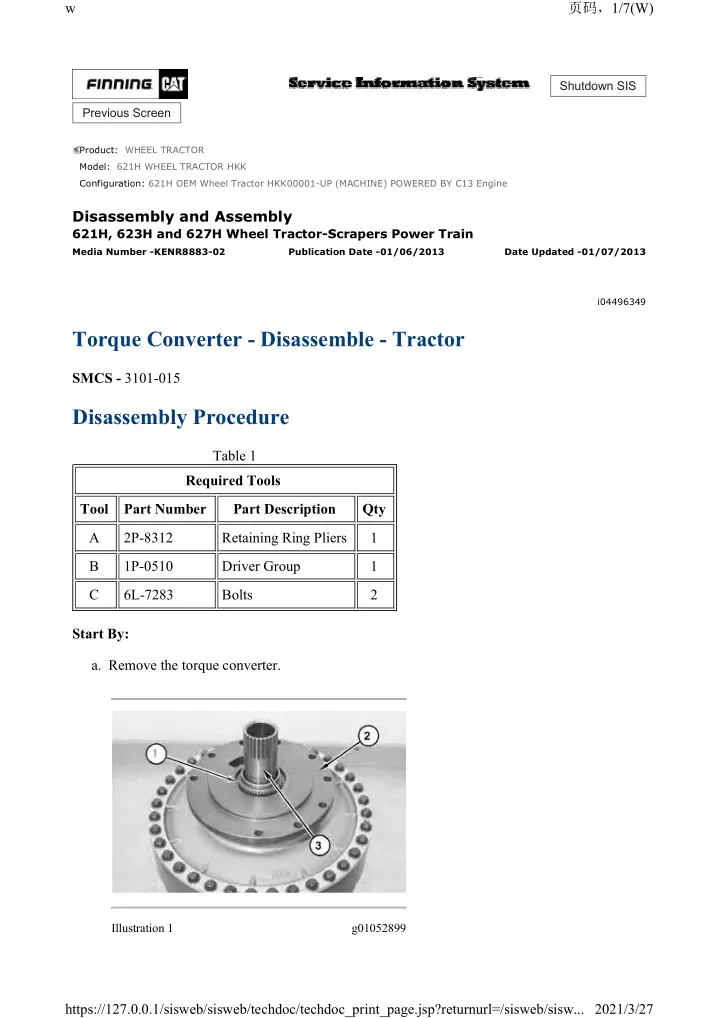
w 1/7(W) Shutdown SIS Previous Screen Product: WHEEL TRACTOR Model: 621H WHEEL TRACTOR HKK Configuration: 621H OEM Wheel Tractor HKK00001-UP (MACHINE) POWERED BY C13 Engine Disassembly and Assembly 621H, 623H and 627H Wheel Tractor-Scrapers Power Train Media Number -KENR8883-02 Publication Date -01/06/2013 Date Updated -01/07/2013 i04496349 Torque Converter - Disassemble - Tractor SMCS - 3101-015 Disassembly Procedure Table 1 Required Tools Tool Part Number Part Description Qty A 2P-8312 Retaining Ring Pliers 1 B 1P-0510 Driver Group 1 C 6L-7283 Bolts 2 Start By: a. Remove the torque converter. Illustration 1 g01052899 https://127.0.0.1/sisweb/sisweb/techdoc/techdoc_print_page.jsp?returnurl=/sisweb/sisw... 2021/3/27
w 2/7(W) 1. Use Tooling (A) in order to remove retaining ring (1) from carriage support assembly (2). Remove carriage support assembly (2) from hub (3). Use Tooling (B) and a suitable press in order to remove the sleeve bearing from carriage support assembly (2). Illustration 2 g00525303 2. Remove bolts (4) and the washers from torque converter impeller (5). Remove bolts (6), the washers, and clamp plate (7) from impeller hub (8). Illustration 3 g00525304 3. Install Tooling (C) in torque converter impeller (5). Use Tooling in order to remove torque converter impeller (5) and impeller hub (8) from housing (9). https://127.0.0.1/sisweb/sisweb/techdoc/techdoc_print_page.jsp?returnurl=/sisweb/sisw... 2021/3/27
w 3/7(W) Illustration 4 g00525305 4. Remove metal seal ring (10) from torque converter impeller (5). Remove impeller hub (8) from torque converter impeller (5). Illustration 5 g00525306 5. Remove thrust bearing (11) from carrier assembly (12). Illustration 6 g00525308 Illustration 7 g00525309 6. Remove carrier assembly (12) and torque converter stator (13) as a unit from housing (9). https://127.0.0.1/sisweb/sisweb/techdoc/techdoc_print_page.jsp?returnurl=/sisweb/sisw... 2021/3/27
w 4/7(W) 7. Position carrier assembly (12) and torque converter stator (13), as shown. Use Tooling (A) in order to remove retaining ring (14) from torque converter stator (13). Remove thrust race (15) from torque converter stator (13). Illustration 8 g00525863 Personal injury can result from being struck by parts propelled by a released spring force. Make sure to wear all necessary protective equipment. Follow the recommended procedure and use all recommended tooling to release the spring force. 8. Remove freewheel rollers (16) and freewheel springs (17) from freewheel cam (18). Remove torque converter stator (13) from carrier assembly (12). Illustration 9 g01080684 9. Use Tooling (A) in order to remove retaining ring (19) from torque converter stator (13). Remove side plate (20) from torque converter stator (13). https://127.0.0.1/sisweb/sisweb/techdoc/techdoc_print_page.jsp?returnurl=/sisweb/sisw... 2021/3/27
w 5/7(W) 10. Use Tooling (B) and a suitable press in order to remove freewheel cam (18) (not shown) from torque converter stator (13). Illustration 10 g01052916 11. Remove thrust bearing (21) from carrier assembly (12). Remove sleeve bearing (22) from carrier assembly (12). Illustration 11 g00525315 12. Remove torque converter turbine (23) and hub (3) as a unit from housing (9). Illustration 12 g01052922 https://127.0.0.1/sisweb/sisweb/techdoc/techdoc_print_page.jsp?returnurl=/sisweb/sisw... 2021/3/27
https://www.aservicemanualpdf.com/ My Dear Friend! Thank you very much for visiting. Full manual if required, please enter the following URL into your browser. https://www.aservicemanualpdf.com/
w 6/7(W) 13. Remove thrust bearing (24) and thrust race (25) from hub (3). Illustration 13 g00525320 14. Position torque converter turbine (23), as shown. Remove thrust race (26) from hub (3). Put an alignment mark on torque converter turbine (23) and hub (3) for installation purposes. Remove bolts (27) from torque converter turbine (23). Illustration 14 g00525321 15. Remove clamp ring (28) and torque converter turbine (23) from hub (3). Illustration 15 g00525322 https://127.0.0.1/sisweb/sisweb/techdoc/techdoc_print_page.jsp?returnurl=/sisweb/sisw... 2021/3/27
w 7/7(W) 16. Remove thrust bearing (29) and thrust race (30) from housing (9). Illustration 16 g00528612 17. Remove bolts (31) and flange (32) from housing (9). Illustration 17 g00525323 18. Remove sleeve bearing (33) from flange (32). Copyright 1993 - 2021 Caterpillar Inc. Sat Mar 27 07:09:34 UTC+0800 2021 All Rights Reserved. Private Network For SIS Licensees. https://127.0.0.1/sisweb/sisweb/techdoc/techdoc_print_page.jsp?returnurl=/sisweb/sisw... 2021/3/27
w 1/8(W) Shutdown SIS Previous Screen Product: WHEEL TRACTOR Model: 621H WHEEL TRACTOR HKK Configuration: 621H OEM Wheel Tractor HKK00001-UP (MACHINE) POWERED BY C13 Engine Disassembly and Assembly 621H, 623H and 627H Wheel Tractor-Scrapers Power Train Media Number -KENR8883-02 Publication Date -01/06/2013 Date Updated -01/07/2013 i07459845 Torque Converter - Assemble - Tractor SMCS - 3101-016 Assembly Procedure Table 1 Required Tools Tool Part Number Part Description Qty A 2P-8312 Retaining Ring Pliers 1 B 1P-0510 Driver Group 1 D 8T-5096 Dial Indicator Group 1 Illustration 1 g00528674 1. Use Tooling (B) and a suitable press to install sleeve bearing (33). Install sleeve bearing (33) to flange (32). https://127.0.0.1/sisweb/sisweb/techdoc/techdoc_print_page.jsp?returnurl=/sisweb/sisw... 2021/3/27
w 2/8(W) Illustration 2 g00528612 2. Install bolts (31) and flange (32) to housing (9). Tighten bolts (31) to a torque of 120 ± 15 N.m (89 ± 11 lb ft). Illustration 3 g00525322 3. Install thrust race (30) and thrust bearing (29) to housing (9). Illustration 4 g00525321 4. Install torque converter turbine (23) and clamp ring (28) to hub (3). https://127.0.0.1/sisweb/sisweb/techdoc/techdoc_print_page.jsp?returnurl=/sisweb/sisw... 2021/3/27
w 3/8(W) Illustration 5 g06329533 5. Install bolts (27) to torque converter turbine (23). Tighten bolts (27) to a torque of 50 ± 7 N.m (37 ± 5 lb ft). Illustration 6 g01052922 6. Install thrust race (25) and thrust bearing (24) to hub (3). Illustration 7 g06329534 7. Install thrust race (26) to hub (3). https://127.0.0.1/sisweb/sisweb/techdoc/techdoc_print_page.jsp?returnurl=/sisweb/sisw... 2021/3/27
w 4/8(W) Illustration 8 g00525315 8. Install torque converter turbine (23) and hub (3) as a unit to housing (9). Illustration 9 g00528953 9. Use Tooling (B) and a suitable press to install sleeve bearing (22). Install sleeve bearing (22) to carrier assembly (12). 10. Install thrust bearing (21) to carrier assembly (12). Illustration 10 g01052912 https://127.0.0.1/sisweb/sisweb/techdoc/techdoc_print_page.jsp?returnurl=/sisweb/sisw... 2021/3/27
w 5/8(W) 11. Install side plate (20) to torque converter stator (13). Use Tooling (A) to install retaining ring (19). Install retaining ring (19) to torque converter stator (13). Illustration 11 g00525863 Personal injury can result from being struck by parts propelled by a released spring force. Make sure to wear all necessary protective equipment. Follow the recommended procedure and use all recommended tooling to release the spring force. 12. Use Tooling (B) and a suitable press to install freewheel cam (18). Install freewheel cam (18) to torque converter stator (13). 13. Install torque converter stator (13) to carrier assembly (12). Install freewheel springs (17) and freewheel rollers (16) to freewheel cam (18). Always install new freewheel springs (17) and freewheel rollers (16). Install freewheel springs (17) with the maximum number of loops in freewheel springs (17) to the outside of freewheel cam (18). Torque converter stator (13) should turn freely in the counterclockwise direction. Torque converter stator (13) should not turn freely in the clockwise direction. https://127.0.0.1/sisweb/sisweb/techdoc/techdoc_print_page.jsp?returnurl=/sisweb/sisw... 2021/3/27
w 6/8(W) Illustration 12 g00525309 14. Install thrust race (15) to torque converter stator (13). Use Tooling (A) to install retaining ring (14). Install retaining ring (14) to torque converter stator (13). Illustration 13 g00525308 15. Install carrier assembly (12) and torque converter stator (13) as a unit to housing (9). Illustration 14 g00525306 16. Install thrust bearing (11) to carrier assembly (12). https://127.0.0.1/sisweb/sisweb/techdoc/techdoc_print_page.jsp?returnurl=/sisweb/sisw... 2021/3/27
w 7/8(W) Illustration 15 g00525305 17. Install impeller hub (8) to torque converter impeller (5). Install metal seal ring (10) to torque converter impeller (5). Illustration 16 g00525303 18. Install clamp plate (7), the washers, and bolts (6) to impeller hub (8). Tighten bolts (6) to a torque of 50 ± 7 N.m (37 ± 5 lb ft). 19. Install bolts (4) and the washers to torque converter impeller (5). Tighten bolts (4) to a torque of 50 ± 7 N.m (37 ± 5 lb ft). Illustration 17 g00525299 20. Use Tooling (B) and a suitable press to install the sleeve bearing in carriage support assembly (2). Install the sleeve bearing until the sleeve bearing is flush with the outside machined surface of carriage support assembly (2). 21. Install carriage support assembly (2) to hub (3). Use Tooling (A) to install retaining ring (1). Install retaining ring (1) to carriage support assembly (2). https://127.0.0.1/sisweb/sisweb/techdoc/techdoc_print_page.jsp?returnurl=/sisweb/sisw... 2021/3/27
w 8/8(W) Illustration 18 g01053220 22. Install Tooling (D) to the torque converter, as shown. The edge of Tooling (D) must be in contact with the edge of carrier assembly (12), as shown. Move hub (3) up and down with a screwdriver. The end play of hub (3) must be 0.13 to 1.96 mm (0.005 to 0.077 inch). End By: a. Install the torque converter. Copyright 1993 - 2021 Caterpillar Inc. Sat Mar 27 07:10:30 UTC+0800 2021 All Rights Reserved. Private Network For SIS Licensees. https://127.0.0.1/sisweb/sisweb/techdoc/techdoc_print_page.jsp?returnurl=/sisweb/sisw... 2021/3/27
w 1/3(W) Shutdown SIS Previous Screen Product: WHEEL TRACTOR Model: 621H WHEEL TRACTOR HKK Configuration: 621H OEM Wheel Tractor HKK00001-UP (MACHINE) POWERED BY C13 Engine Disassembly and Assembly 621H, 623H and 627H Wheel Tractor-Scrapers Power Train Media Number -KENR8883-02 Publication Date -01/06/2013 Date Updated -01/07/2013 i04573776 Transfer Gears - Remove and Install - Tractor, Off Chassis SMCS - 3159-010 Removal Procedure Table 1 Required Tools Tool Part Number Part Description Qty A 138-7574 Link Bracket 2 B 308-3471 Jack Stand Gp 1 Start By: a. Remove the transmission, torque converter, and transfer gears. b. Remove the speed sensor. https://127.0.0.1/sisweb/sisweb/techdoc/techdoc_print_page.jsp?returnurl=/sisweb/sisw... 2021/3/27
w 2/3(W) Illustration 1 g02731531 1. Use Tooling (A) and a suitable lifting device to position transmission, torque converter, and transfer gears (1) onto suitable cribbing and Tooling (B). The weight of transmission, torque converter, and transfer gears (1) is approximately 1320 kg (2910 lb). Illustration 2 g02731558 https://127.0.0.1/sisweb/sisweb/techdoc/techdoc_print_page.jsp?returnurl=/sisweb/sisw... 2021/3/27
w 3/3(W) Illustration 3 g02731561 2. Attach Tooling (A) and a suitable lifting device to transfer gears (2). The weight of transfer gears (2) is approximately 340 kg (750 lb). Remove nuts (3) and the bolts. Separate transfer gears (2) from transmission (4). Remove O-ring seals (5). Illustration 4 g02731564 3. Remove O-ring seal (6). Installation Procedure 1. Install transfer gears (2) in the reverse order of removal. Copyright 1993 - 2021 Caterpillar Inc. Sat Mar 27 07:11:26 UTC+0800 2021 All Rights Reserved. Private Network For SIS Licensees. https://127.0.0.1/sisweb/sisweb/techdoc/techdoc_print_page.jsp?returnurl=/sisweb/sisw... 2021/3/27
w 1/4(W) Shutdown SIS Previous Screen Product: WHEEL TRACTOR Model: 621H WHEEL TRACTOR HKK Configuration: 621H OEM Wheel Tractor HKK00001-UP (MACHINE) POWERED BY C13 Engine Disassembly and Assembly 621H, 623H and 627H Wheel Tractor-Scrapers Power Train Media Number -KENR8883-02 Publication Date -01/06/2013 Date Updated -01/07/2013 i04572074 Transfer Gears - Remove and Install - Tractor, In Chassis SMCS - 3159-010 Removal Procedure Table 1 Required Tools Tool Part Number Part Description Qty A 138-7575 Link Bracket 1 B 138-7574 Link Bracket 1 C - 1/2 - 13 NC by 1.5 inch Bolts 2 Hot oil and components can cause personal injury. Do not allow hot oil or components to contact skin. 1. Start the machine. Turn the tractor so that the tractor is at a right angle to the scraper. 2. Remove the power train guard (transmission). 3. Remove the drive shaft. 4. Remove the speed sensor. 5. Remove gear pump (steering). https://127.0.0.1/sisweb/sisweb/techdoc/techdoc_print_page.jsp?returnurl=/sisweb/sisw... 2021/3/27
w 2/4(W) 6. Remove piston pump (implement) 7. Remove the piston pump (elevator), if equipped. 8. Remove the transmission scavenge pump. Illustration 1 g02731336 9. Disconnect clip (2) . Disconnect hose assemblies (3) and harness assembly (1) from filter assembly (4). 10. Attach Tooling (A) and a suitable lifting device to filter assembly (4). The weight of filter assembly (4) is approximately 36 kg (80 lb). Remove filter assembly (4). Illustration 2 g02731337 11. Disconnect hose assemblies (5). 12. Remove hose assembly (8) and (11). 13. Remove tube assemblies (7) and (9). 14. Disconnect harness assembly (10) from transfer gears (6). https://127.0.0.1/sisweb/sisweb/techdoc/techdoc_print_page.jsp?returnurl=/sisweb/sisw... 2021/3/27
w 3/4(W) Illustration 3 g02731365 15. Remove tube assembly (12). Illustration 4 g02731366 Illustration 5 g02731367 16. Attach Tooling (A) and a suitable lifting device to transfer gears (6). The weight of transfer gears (6) is approximately 318 kg (700 lb). 17. Remove bracket (14). https://127.0.0.1/sisweb/sisweb/techdoc/techdoc_print_page.jsp?returnurl=/sisweb/sisw... 2021/3/27
w 4/4(W) 18. Remove nuts (13) and the bolts that secure transfer gears (6) to the transmission case. Use Tooling (C) to remove transfer gears (6). Remove transfer gears (6). Illustration 6 g02731368 19. Remove O-ring seals (15). Illustration 7 g02731369 20. Remove O-ring seal (16). Installation Procedure 1. Install transfer gears (6) in the reverse order of removal. Copyright 1993 - 2021 Caterpillar Inc. Sat Mar 27 07:12:22 UTC+0800 2021 All Rights Reserved. Private Network For SIS Licensees. https://127.0.0.1/sisweb/sisweb/techdoc/techdoc_print_page.jsp?returnurl=/sisweb/sisw... 2021/3/27
w 1/10(W) Shutdown SIS Previous Screen Product: WHEEL TRACTOR Model: 621H WHEEL TRACTOR HKK Configuration: 621H OEM Wheel Tractor HKK00001-UP (MACHINE) POWERED BY C13 Engine Disassembly and Assembly 621H, 623H and 627H Wheel Tractor-Scrapers Power Train Media Number -KENR8883-02 Publication Date -01/06/2013 Date Updated -01/07/2013 i07460047 Transfer Gears - Disassemble - Tractor SMCS - 3159-015 Disassembly Procedure Table 1 Required Tools Tool Part Number Part Description Qty A 439-3940 Bracket As 1 8B-7548 Push-Puller Tool Gp 1 B 8B-7551 Bearing Puller Gp 1 1P-0498 Drive Plate 1 5P-4170 Step Plate 1 C 1P-2321 Combination Puller 1 8B-7554 Bearing Cup Puller Gp 1 D 5P-4170 Step Plate 1 1P-0518 Drive Plate 1 8B-7560 Step Plate 1 E 5F-7345 Screw 1 8B-7554 Bearing Cup Puller Gp 1 Bolts 3/8" - 16 NC by 3 inch F - 3 Start By: https://127.0.0.1/sisweb/sisweb/techdoc/techdoc_print_page.jsp?returnurl=/sisweb/sisw... 2021/3/27
w 2/10(W) a. Remove the transfer gear case. b. Remove the transmission oil filter base. c. Remove the transmission scavenge pump. d. Remove the transmission oil pump. NOTICE Keep all parts clean from contaminants. Contamination of the hydraulic system with foreign material will reduce the service life of the hydraulic system components. To prevent contaminants from entering the hydraulic system, always plug or cap the lines, fittings, or hoses as they are disconnected. Cover any disassembled components and clean them properly before assembly. Clean the hydraulic system properly after any major component exchange or especially after a component failure, to remove any contamination. 1. Put identification marks on components for installation purposes. Illustration 1 g02603076 2. Remove the bolts that secure bearing cage (1) to the transfer gear case. Use Tooling (F) to separate bearing cage (1) from the transfer gear case. 3. Remove bearing cage (1) and shims (2) from the transfer gear case. https://127.0.0.1/sisweb/sisweb/techdoc/techdoc_print_page.jsp?returnurl=/sisweb/sisw... 2021/3/27
w 3/10(W) Illustration 2 g02602859 4. Remove the bolts that secure bearing cage (3) to the transfer gear case. Use Tooling (F) to separate bearing cage (3) from the transfer gear case. 5. Remove bearing cage (3) and shims (4) from the transfer gear case. Illustration 3 g02603657 6. Remove gear assembly (5). Illustration 4 g02603659 7. Remove tube (6) and gear assembly (7). https://127.0.0.1/sisweb/sisweb/techdoc/techdoc_print_page.jsp?returnurl=/sisweb/sisw... 2021/3/27
w 4/10(W) Illustration 5 g02602876 8. Remove bearing cups (8) from the transfer gear case. Attach Tooling (A) and a suitable lifting device onto the transfer gear case. The weight of the transfer gear case is approximately 340 kg (750 lb). Turn over the transfer gear case. Remove Tooling (A). Illustration 6 g01102873 9. Remove the bolts that secure bearing cage (9) to the transfer gear case. Use Tooling (F) to separate bearing cage (9) from the transfer gear case. 10. Remove bearing cage (9), shims (10), and gear (11) from the transfer gear case. Illustration 7 g00529214 https://127.0.0.1/sisweb/sisweb/techdoc/techdoc_print_page.jsp?returnurl=/sisweb/sisw... 2021/3/27
w 5/10(W) 11. Remove bearing cup (12) from the transfer gear case. Attach Tooling (A) and a suitable lifting device onto the transfer gear case. Turn over the transfer gear case. Illustration 8 g00529215 12. Remove bolts (13) that secure bearing cage (14) to the transfer gear case. If necessary, rotate the gear until the three threaded holes are visible in bearing cage (14). Install Tooling (F) through gear (15) and into bearing cage (14). Tighten Tooling (F) evenly until bearing cage (14) and gear (15) separate from the transfer gear case. Remove bearing cage (14) and gear (15) as a unit from the transfer gear case. Illustration 9 g00529216 Illustration 10 g00529257 https://127.0.0.1/sisweb/sisweb/techdoc/techdoc_print_page.jsp?returnurl=/sisweb/sisw... 2021/3/27
w 6/10(W) 13. Remove retaining ring (16) from gear (15). Remove bearing (17) and bearing cage (14) from gear (15). Illustration 11 g01048544 14. Remove bearing (17) from bearing cage (14). Illustration 12 g01048548 15. Remove bolts (19) and separate gear (20) from gear (11). Use Tooling (B) to remove bearing cone (18). Remove bearing cone (18) from gear (11). Repeat the procedure for the bearing cone on the opposite side of gear (11). Illustration 13 g02660644 https://127.0.0.1/sisweb/sisweb/techdoc/techdoc_print_page.jsp?returnurl=/sisweb/sisw... 2021/3/27
Please write to us. Our email: aservicemanualpdf@yahoo.com Please go to the homepage to get the full manual, or other brand PDF manuals. Home Site: aservicemanualpdf.com
GET MORE OTHER MANUALS https://www.aservicemanualpdf.com/ Thank you very much for your reading. Please Click Here. Then Get COMPLETE MANUAL. NO WAITING NOTE: If there is no response to click on the link above, please download the PDF document first and then click on it. GET MORE OTHER MANUALS https://www.aservicemanualpdf.com/
w 7/10(W) 16. Use Tooling (C) to remove bearing cone (21). Remove bearing cone (21) from gear (5). Repeat the procedure for the bearing cone on the opposite side of gear (5). Illustration 14 g02661176 17. Use Tooling (C) to remove bearing cone (21). Remove bearing cone (21) from gear (7). Repeat the procedure for the bearing cone on the opposite side of gear (7). Illustration 15 g02661799 18. Use Tooling (D) to remove bearing cup (23). Remove bearing cup (23) from bearing cage (1). Remove O-ring seal (24) from bearing cage (1). Illustration 16 g01048553 https://127.0.0.1/sisweb/sisweb/techdoc/techdoc_print_page.jsp?returnurl=/sisweb/sisw... 2021/3/27
w 8/10(W) 19. Remove bearing cup (25) from bearing cage (9). Illustration 17 g02662017 20. Use Tooling (E) to remove bearing cup (26). Remove bearing cup (26) from bearing cage (3). Remove O-ring seal (27) from bearing cage (3). Illustration 18 g02603736 21. Remove the bolt that secure cover (28). Use Tooling (F) to remove cover (28). Remove cover (28). Illustration 19 g02603807 https://127.0.0.1/sisweb/sisweb/techdoc/techdoc_print_page.jsp?returnurl=/sisweb/sisw... 2021/3/27
w 9/10(W) 22. Remove the bolt that secure bearing cage (29). Use Tooling (F) to remove bearing cage (29) and shims (30). Remove bearing cage (29) and shims (30). Illustration 20 g02603842 23. Remove tube (31) and gear assembly (32). Illustration 21 g02662457 24. Use Tooling (C) to remove bearing cone (33). Remove bearing cone (33) from gear (32). Repeat the procedure for the bearing cone on the opposite side of gear (32). Illustration 22 g02603857 https://127.0.0.1/sisweb/sisweb/techdoc/techdoc_print_page.jsp?returnurl=/sisweb/sisw... 2021/3/27
https://www.aservicemanualpdf.com/ My Dear Friend! Thank you very much for visiting. Full manual if required, please enter the following URL into your browser. https://www.aservicemanualpdf.com/