Download

1 / 32
340 likes | 514 Views
Muon Collider: Plans, Progress and Challenges Ronald Lipton, Fermilab. Outline Muon Collider Concept Muon Accelerator Program Machine Detector Interface Studies Physics and detector studies Future plans and outlook. Muon Collider Study Motivation.

E N D
Muon Collider: Plans, Progress and ChallengesRonald Lipton, Fermilab Outline • Muon Collider Concept • Muon Accelerator Program • Machine Detector Interface Studies • Physics and detector studies • Future plans and outlook
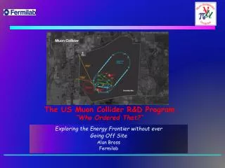
Muon Collider Study Motivation • Because muons don’t radiate as readily as electrons (mm / me ~ 207) a muon collider can be circular rather then linear • Compact • Fits on laboratory site • Multi-pass acceleration • Cost effective operation & construction • Multipass collisions in a ring (~1000 turns) • Relaxed emittance requirements & hence relaxed tolerances Much of the material in this talk from June Workshop in Telluride A 4 TeVMuon Collider wouldfit on the Fermilab Site
Challenges • Muons decay A 1.5 TeVmuon travels 9,300 km in one lifetime (~2000 turns in MuCol ring). Everything must be done fast and we must deal with the decay electrons. • Muons are produced as tertiary particles. To make enough of them we must start with a MW scale proton source & target facility. • Muons are born within a large phase-space. For a MC we must cool them by O(106) before they decay New cooling techniques (ionization cooling) must be demonstrated, and it requires components with demanding performance (NCRF in magnetic channel, high field solenoids.) • After cooling, beams still have relatively large emittance
Muon Collider Schematic √s = 3 TeV Circumference = 4.5kmL = 2×1034 cm-2s-1m/bunch = 2x10¹² s(p)/p = 0.1% eN = 25 mm, e//N=70 mm b* = 5mm Rep Rate = 12Hz 1021muons per year that fit within the acceptance of an accelerator: eN=6000 mm e//N=25 mm Proton source: Example: upgraded PROJECT X (4 MW, 2±1 ns long bunches) (Geer)
Neutrino Factory c.f. Muon Collider NEUTRINOFACTORY MUONCOLLIDER In present MC baseline design, Front End is same as for NF (Geer)
Muon Accelerator Program • Oct 1, 2009 letter from DOE-OHEP to FNAL Director: “Our office believes that it is timely to mount a concerted national R&D program that addresses the technical challenges and feasibility issues relevant to the capabilities needed for future Neutrino Factory and multi-TeVMuon Collider facilities. ...” • Letter requested a new organization for a national Muon Collider & Neutrino Factory R&D program, hosted at FNAL. • MuonAccelerator Program organization is now in place & functioning: >200 participants from 15 institutions: • ANL, BNL, FNAL, JLab, LBNL, ORNL, SLAC, Cornell, IIT, Princeton, UCB, UCLA, UCR, U-Miss, U. Chicago • http://map.fnal.gov/
Accelerator Challenges • Ionization Cooling • Very high field (40T) high temp superconducting magnets • 6 dimensional cooling • RF breakdown in magnetic fields • Neutrino radiation ( < 10% x DOE limit at site boundary?) • Probably OK at 1.5 TeV, harder at 3 TeV • Must limit length of straight sections (~ meters) – go deeper? • Magnet shielding from beam decay heat loads Are any of these deadly to the Muon Collider concept? – MAP should be able to tell us. • More details from M. Zisman talk yesterday
+ RL modifications CLIC 3 2 14 4/.07 mm 29 ~415 Wall Power 147 159 MW 0.001 Beam Size at IP 4 4 mm 660/20 nm
Muon Accelerator R&D 1 cm Merit at CERN - Demonstrated a 20m/s liquid Hg jetinjected into a 15 T solenoid, & hit with a 115 KJ / pulse beam. Muon Ionization Cooling Experiment (MICE) AT RAL • Tests short cooling section, in muon beam, measuring single muons before & after the cooling section. • Learn about cost, complexity,& engineering issues associated with cooling channels. • Vary RF, solenoid & absorber parameters & demonstrateability to simulate response of muons To be completed ~2014 Hg jet in a 15 T solenoid Measured disruption length = 28 cm Spectro-meter Cooling section Spectro-meter
Front End andCooling Channel Design Front End • With a 4MW proton source, this will enable O(1021) muons/year to be produced, bunched, cooled & fit within the acceptance of an accelerator Cooling Channel • Perhaps the most challenging piece of MC design. Requires ideas& detailed design work to identify a set of hardware that cando the job.
Ring and MagnetMucool Ring and Magnet • Lattice design for 1.5 TeV Collider exists, & 3 TeVring progressing. • Requires lattice, magnet & MARS simulation • Studying open mid-plane magnet design (radiation & heat loads, field non-uniformity & affect on lattice performance) MuCoolTest Area • Built at end of FNAL Linac for ionization cooling testing • 5 T magnet, RF power at 805 MHz & 201 MHz, clean room, LH2handling capability,400 MeV beam from linac. • Study RF breakdown in magnetic fields → critical R&D at MTA First beam in MTA 28 February 2011 MARS energy deposition map for 1.5 TeV collider dipole
Physics and Detector • Although there is a revived muon accelerator effort, there has been little corresponding detector effort which could study the large beam-related backgrounds with modern simulation tools and detector technologies • Beginning such an effort is crucial to understanding the physics reach of such a device and beginning a program to explore detector development for the muon collider environment. • It is also crucial for community buy-in • This effort was commissioned at the Muon Collider 2011 meeting in Telluride at the end of June.
Physics Environment Beamstrahlung in any e+e- collider E/E 2 • Narrow beam energy spread • Precision scan • Kinematic constraints • 2 Detectors • DTbunch ~ 10 ms • Lots of time for readout • Backgrounds don’t pile up • (mm/me)2 = ~40000 • Enhanced s-channel rates for Higgs-like particles • Multi-TeV lepton collider cross sections dominated by fusion (Han)
(Eichten) Luminosity Goals for High Energy MuonCollider • L~1034 at 3 TeV provides ~ 965 events/unit R • Much of the yield is in fusion reactions • Need to resolve W, Z jets • Large missing energies • Physics environment similar to CLIC with lower beamstrahlung, higher decay backgrounds, lower polarization and central 10 degrees obscured by “the nose”
For Experimenters - It’s All About the Background Experiments at the Muon Collider will endure very harsh background environments. The first order of business in evaluating physics capabilities is to understand and simulate the machine backgrounds. • IP m+m- collisions – real physics: Production x-section 1.34 pb at √S = 1.5 TeV. • IP incoherent e+e- pair production: of 3×10⁴ electron pairs per bunch crossing • Muon beam decays: For 0.75-TeV muon beam of 2x10¹², 4.28x10⁵dec/m per bunch crossing, or 1.28x10¹⁰dec/m/s for 2 beams; 0.5 kW/m. • Beam halo: Beam loss at limiting apertures; severe, can be taken care of by an appropriate collimation system far upstream of IP.
The Nose • Ivan Yakovlevitch… glanced into the roll's middle. To his intensesurprise he saw something glimmering there.. He stuck inhis fingers, and pulled out — a nose! .. .A nose! Sure enough a nose! Yes, and one familiar to him, somehow! Oh, horror spread upon his features! - “The Nose” Gogol (from google) • A 10 degree tungsten/borated poly “noise”surrounds the beam pipe to absorb the e-m backgrounds 100-1000x background reduction.
Machine Detector Interface Model There has been excellent progress in modeling the intense decaybackgrounds . Accurate background simulations are now available from MARS and G4beamline Q = 10o 6 < z < 600 cm x:z = 1:17 Q1 W BCH2
Neutron Background Non-ionizing background ~ 0.1 x LHC But crossing interval 10ms/25 ns 400 x
Much of the Background is Soft 164 TeV 5.8 TeV 92 TeV 92 TeV 172 TeV 12 TeV (Striganov)
And Out of Time (Striganov)
Detector Models based on ILC (SiD, ILD, 4Th) LCSIM Detector Model ILCROOT Detector Model
ILCROOT Background Studies (Dual Readout Calorimeter) Central barrel 4x4 cm em+had cell (DiBenedetto)
LCSIM Background Studies An example of background reduction utilizing timing • ECal: Tungsten, • 10 x 1cm layers 1x1x1cm cells • Background • 1ns timing cut Background: No timing Cut 10 GeV e EM cal layer Reduction: Electromagnetic – 23% of energy survives a 1 ns timing cut 6% of that energy is beyond 1st EM cell Hadronic- 0.95% of energy survives a 1 ns cut
A CompensatableMuon Collider Calorimeter (R. Raja, Fermilab) • Pixelated calorimeter with “travelling trigger” • Each pixel is triggered by a 2 ns gate. • The beginning of the gate coincides with the time taken for light to travel from IP to the pixel. • End of trigger = t light + 2 ns. The 2ns gate is chosen to make sure that each pixel can respond to 1 MIP particle going through it and say yes or no. • Each pixel will have a different start and end gate. • 3x10⁻² - 4x10⁻⁴ background rejection Hadron EM separable by pattern recognition—Software compensation possible 100 GeV pion in pixel calorimeter
Background Muon Segments (Raja) Without Travelling Trigger With Travelling Trigger
Track Information (LCSIM) DT • Tracking can benefit from precise timing, low occupancy in a pixelated silicon detector. DE/DX DT +/- 5 ns Background DE/DX DT DT +/- 5 ns Single Muon DE/DX
ILCROOT Tracking Studies Recently demonstrated track finding in a full background event • Cuts on IP, DEDX, and DT=Tcoll –TOF • Dominated by neutrons and photons • This is not energy weighted, many are soft tracks (Mazzacane) (Terentiev)
What we have learned so far • Precise timing and pixelated detectors will be crucial • Tracking seems possible in such a detector • Calorimetery is more challenging (and expensive), but progress is being made on imaging calorimeter concepts • Tracking detectors will resemble LHC detectors (higher mass) more than ILC detectors • Machine • Any significant polarization (>10%) will come at the cost of luminosity • “Local” energy scans not difficult – large energy variations have not been carefully studied
Collaboration on Lepton Collider R&D • Laboratory “White Paper” on Lepton Colliders last summer established the goals of future cooperative efforts: • Establish the requirements of detector systems so the physics can be extracted, taking into account the very different operating conditions at each machine. • Provide feedback to the machine design to further optimize the physics potential. • Propose necessary detector and other R&D to verify detector technologies. • Compare the physics potential of these machines and carry out a cost‐benefit analysis. • Coordinate the detector and physics program. • First joint effort was to submit a unified proposal to the “Collider Detector R&D” program (program not funded in FY2011);\: • Included support for Muon Collider simulation at FNAL and SLAC • Muon Collider detector R&D would come later
Plans • Summer 2011 – Spring 2012 • Studies of toy detectors in full background – establish performance envelopes • Parameterize backgrounds to enable faster physics simulation • Initial physics study including full background simulation Iterate both the shielding and detector designs based on results of simulation studies. • 2012-2013 Define detector requirements, and identify needed detector R&D, begin studies to establish a long-term simulation and analysis environment. • 2014- 2015 Detector R&D + simulation studies to establish likely detector performance • 2015-2017 Define overall detector design, complete studies for the design feasibility report.
Conclusions and Comments • Muon Accelerator Project is up and running – making substantial progress • We are beginning a renewed physics and detector program to study the 1.5-3 TeVMuon Collider environment • We have a strong foundation – reliable MARS simulation of backgrounds integrated into GEANT-based detector models. As a field we need to be in a position to make an informed decision about the tradeoffs of alternate approaches. We need to understand the options if physics points to a multi-TeV lepton collider. CLIC is a strong possibility, but not a “no brainer”, especially as the required energy increases. There are strong overlaps of interest of Muon Collider with CLIC in physics, fast timing, detector design, and simulation.
Remaining backgrounds-Calorimeter (Raja) Tracking also works well with travelling gate trigger