Download
1 / 57
570 likes | 706 Views
Belle upgrade: Tracking and Vertexing. T.Kawasaki(Niigata-U). Introduction. High luminosity B factory High precision measurement with high statistics to search the new physics in B decays Many modes which are sensitive to new physics need High Hermeticity

E N D
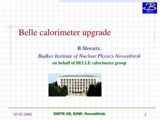
Belle upgrade:Tracking and Vertexing T.Kawasaki(Niigata-U) BNM2008 Atami, Japan
Introduction • High luminosity B factory • High precision measurement with high statistics to search the new physics in B decays • Many modes which are sensitive to new physics need • High Hermeticity • Good efficiency on Low momentum & Ks daughter tracking, (tCPV) Ks vertexing (tCPV) Hermeticity BNM2008 Atami, Japan
Requirements for sBelle Tracker • Robust against high beam background • We assume ×20 BG @2×1035 • ~8% @the first layer of Belle SVD(r=2cm) • Fine segmentation • Fast pulse shaping & time slice information • High trigger rate • Need high speed & deadtimeless readout • More tracking efficiency • Shallow angle tracking. Hermeticity • Low momentum tracking • Ks reconstruction • Better Resolution (At least competitive performance as current SVD) • Thin sensor (⇒refer the next talk for material effect) • Small BP radius Belle SVD Hit finding eff. vs. Occ. 15% Occupancy By Fujiyama(TIT) BNM2008 Atami, Japan
CsI(Tl) 16X0 g pure CsI (endcap) Super Belle detector (LoI ‘04) m / KL detection 14/15 lyr. RPC+Fe g tile scintillator Tracking + dE/dx small cell + He/C2H6 • remove inner lyrs. use fast gas Si vtx. det. 4 lyr. DSSD g 2 pixel/striplet lyrs. + 4 lyr. DSSD SC solenoid 1.5T Aerogel Cherenkov counter + TOF counter g “TOP” + RICH New readout and computing systems BNM2008 Atami, Japan
Super Belle Vertex Tracker(LoI ‘04) Two thin pixel layer Aim 1cm radius beam pipe (cm) r =150mm 6 sensor layers to make low momentum tracking (cm) Slanted layer to keep acceptance, optimize incident angle and save detector size BNM2008 Atami, Japan
Upgrade Schedule Along to the current upgrade schedule Stop Belle 2007 2008 2009 2010 2011 2012 Stop Belle on the end of 2008 (JPY) Start sBelle operation from the beginning of 2012 R&D KEKB&Belle upgrade Start sBelle Reconstruction of detector takes 3 years ⇒We have only 1 year for R&D work!! We need REALISTIC upgrade plan for T=0 operation in 2012 ( with ~1035 ) Further upgrade can be done after getting higher luminosity (1cm beampipe, Thin Monolithic Pixel sensor …… needs further R&D work) BNM2008 Atami, Japan
Central Drift Chamber • Large cover area in radius • 88~863 mm ⇒ 172~1118 mm • Inner part replaced by Si Tracker • 50 ⇒ 58 layers • Small cell to reduce occupancy • ⇒ 2.5mm • 8k ⇒15k sense wires • Same gas mixture :He + C2H6 • Fast FADC readout CDC • Occupancy esitimation • Hit rate : ~100kHz ~5kHz(current) x 20 • Maximum drift time : 80-300nsec • Occupancy : 1-3% 100kHz X 80-300nsec = 0.01-0.03 • Momentum resolution(SVD+CDC) • sPt/Pt = (0.11~0.19)Pt 0.30/b[%] :possible thanks to large cover in radius BNM2008 Atami, Japan
Silicon Vertex Tracker • Occupancy estimation • Assuming Occ ∝ Tp, channel area, 1/r2 • Current SVD VA1(Tp=800ns): ~8%@ 1st layer L =2×1035 ⇒ 8% × 20BG = 160%! • Ex)APV25 (developed for CMS Si Tracker) • Tp=50ns ⇒ Factor 16 reduction is possible ⇒Standard DSSD is OK • ・160 pipeline FIFO • ⇒ pulse shape scan with 40MHz Clk • Further BG reduction is possible • 32 step FIFO event queues • Deadtimeless readout@ 10kHz trigger rate Shaper 0 100 200 ns BNM2008 Atami, Japan
SVT upgrade Strategy • T=0 option (2012) for L= ~1035 • Keep beampipe radius 1.5cm same as current • Current SVD configuration + 2 outer layers • Improve Ks efficiency. Replace CDC inner layers • Similar design DSSD can be used • Fast Shaping(~50ns) + Timeslice on EF chip • Further upgrade for L>1035 • Smaller beampipe radius (r =1cm or less) • Innermost (thin) Pixel layers • Improve impact parameter resolution BNM2008 Atami, Japan
CDC CDC SVD SVD Study on Detector configuration Modify the current Belle simulator in order to evaluate new detector configuration Put L3-4 ladder as outer layer No sensor at forward region Belle sBelle SVD L1-L4 @ r = 2.0, 4.35, 7.0, 8.8 cm CDC r= 8.8~86.3cm SVD Add L5&L6 @ r = (13), 14cm CDC r=16.0~112.0cm BNM2008 Atami, Japan
Impact Parameter resolution Calculated by TRACKERR r-fdirection [cm] z direction [cm] 0.02 0.03 LoI ‘04 sBelle SVD2(now) For p- 0.2GeV 0.5GeV 1.0GeV 2.0GeV 0.01 0 1.4 sinq Beampipe radius is important Competitive performance as current SVD Degradation of intrinsic resolution is included Efficiency loss is NOT included BNM2008 Atami, Japan
Momentum resolution Calculated by TRACKERR k resolution [rad] fresolution [10-3/cm] 0.02 0.3 LoI ‘04 sBelle SVD2(now) For p- 0.2GeV 0.5GeV 1.0GeV 2.0GeV 0.01 0.1 0 1.4 sinq Competitive performance as current SVD More layer doesn’t worsen momentum resolution Degradation of intrinsic resolution is included Efficiency loss is NOT included BNM2008 Atami, Japan
Ks reconstruction : 5th layer position GEANT3 Full simulation by Shinomiya Eff. Ks Ks Vtx resolution Move 5th layer to outer More Ks but poor vtx resolution =0.68 Ks B vertex: Ks pseudo track + Beam profile e- e+ Beam profile Relative luminosity to measure Acp BNM2008 Atami, Japan
Requirement on S/N ratio ・Assuming signal=MIP@300mm Si ・Noise determined with Sensor Leakage current Detector Capacitance 3DSSDs are readouted via FLEX ⇒Chain readout makes large detector capacitance Noise performance⇒Depends on FE chip sBelle Belle VA1 @ Tp=1ms enc [e-]=180+ 7.5/Cd[pF] ⇒ Leakage current dominates APV25 @ Tp=50ns enc [e-]= 246 + 36/Cd[pF] ⇒Detector capacitance is crucial 3DSSD:~60pF630e- ⇒ 2500e- (Only Det. Capacitance components) BNM2008 Atami, Japan
Effect of poor S/N ratio on the outer layers GEANT3 Full sim. M.E.(Matching Efficiency) = Prob.(SVD hits are found on at least 2 SVD layers) CDC M.E. M.E. SVT Only 5&6 Layers All Layers Kalman filtering Extrapolate track from CDC 10 ×Typ. 10 ×Typ. Noise Noise S/N degradation on the outer layer doesn’t affect to M.E. so much But, In case of Ks daughter track… BNM2008 Atami, Japan
Matching efficiency for Ks 1.0 normal Matching efficiency Noise x 2 Noise x 4 0 0 10 20 [cm] GEANT3 Full sim By Nakagawa SVD Matched track L3 L4 L5 L3 L4 L5 normal Noise x 4 0 10 20 [cm] r of Ks decay vertex r of Ks decay vertex M.E. for Ks daughters are affected by S/N degradation Lose 20% (SVT) events with 4 times worse S/N BNM2008 Atami, Japan
BG effect on analysis • Major loss comes from low tracking efficiency for slow particles • Efficiency loss on high multiplicity event is serious • Moreover a pulse shape information by FADC readout can save efficiency • Gain by SVD standalone tracker is not included Preliminary By Ozaki BNM2008 Atami, Japan
Key technology for upgrade • Timeslice Information/Full Pipeline readout • Pipeline in FE chip(APV25, VA-mod, own ASIC) • Practical implementation scheme in a limited space • Ladder assembling. Mechanical Support structure • Cooling/Cabling • Save S/N for outer layer. • FLEX readout. Chip on sensor • Sensor development (No more HPK DSSD) • Low noise & Large area sensor is desirable • Thin (less material) Thick (more signal) • Pixel sensor (Option for future upgrade) • Thin & Fast readout. Monolithic device? BNM2008 Atami, Japan
Status of R&D Activity FADC: 40MHz digitization Online sparsification with FPGA Hybrid card with 4 APV25 chips Operated with 40MHz clock (Princeton) • We have been working to prepare Pipeline readout module Beamtest done in KEK in Nov 2007 Confirm the capability of sparsification algorithm BNM2008 Atami, Japan
Chip on sensor with FLEX hybrid Proposal by Vienna group Readout each DSSD by putting FE chip on sensor Cooling with water trough carbon fiber tube No Cooling Cooling with 13℃ water BNM2008 Atami, Japan
Schedule for CDC/SVT upgrade Stop Belle Start sBelle 2007 2008 2009 2010 2011 2012 Test Design CDC End Plate Machining Wire stringing Cabling/Tubing Installation &Final Test Cosmic Test Sensor Production Test SVT Design Assembling Installation Final Test NOT official one BNM2008 Atami, Japan
Summary • We have started activity for the practical detector design • CDC • Same gas mixture as Belle • Better resolution with larger coverage in radius • Robust against BG with small cell and time digitization • SVT • 2cm Beampipe + 6 DSSD layers • Employ DSSD with short shaping as T=0 • Competitive resolution • IR design. Need close discussion and closer collaborative work with accelerator people on • Please join!! Any contribution are welcome! BNM2008 Atami, Japan
Pixel sensor R&D Items to be achieved for High luminosity B factory • Readout Speed • Radiation Hardness • Thin Detector • Full-sized detector MAPS is the unique solution. Development of MAPS (Monolithic Active Pixel sensor) is in world wide competition (ex:CAPS(Hawaii), SOIPIX (KEK)) Progress in the coming a few years is very important. BNM2008 Atami, Japan
Backups BNM2008 Atami, Japan
Bkg & TRG rate in future x20 Bkg x10 Bkg KEKB Bkg SVD CDC PID / ECL KLM Synchrotron radiation Beam-gas scattering (inc. intra-beam scattering) Radiative Bhabha BNM2008 Atami, Japan
Hit rate Apr.-5th ,2005 IHER = 1.24A ILER = 1.7A Lpeak = 1.5x1034cm-2sec-1 ICDC = 1mA Small cell Inner Main 10KHz BNM2008 Atami, Japan
Simulation Study for Higher Beam Background by K.Senyo. MC +BGx1 MC+BGx20 BNM2008 Atami, Japan
Hit rate at layer 35 Dec.,2003 LER HER IHER = 4.1A Hit rate = 13kHz ILER = 9.4A Hit rate = 70kHz Dec., 2003 : ~5kHz Now : ~4kHz In total 83kHz BNM2008 Atami, Japan
CDC : Main parameters BNM2008 Atami, Japan
Intrinsic Resolution vs. Occupancy Intrinsic Resolution occupancy < 0.04 occupancy 0.3 residual residual At high occupancy, g cluster shape is 'distorted' g reconstructed cluster energy to be off g the residual distribution to be widened S.Fratina g Occupancy BNM2008 Atami, Japan
Hit Efficiency vs. Occupancy Efficiency Layer No. hit or not? 1 2 Layer2 Layer1 • Higher Occupancy • ~ Lower Hit Efficiency • Signal + background hits • g wider 'distorted' cluster • Wrongly associated background cluster 1.0 h 0.6 Layer4 Layer3 3 4 0% g 30% Occupancy BNM2008 Atami, Japan Y.Fujiyama
Occupancy problem at innermost layer L=1035/cm2/s SVD2(800nsec) • Estimate occupancy at Super B • Occupancy at SVD2 • At most, 10% in r =20mm for 1034/cm2/s • AssumingOcc. = luminosity/r2 • r =15mm for 1035/cm2/s a occupancy = 200% Factor 40 of reduction is needed!! • How can we reduce Occ.? • Assuming Occ. = sensitive area* shaping time • Short shaping time • Tp=100ns is possible (Factor 8) (SVD2:VA1TA, Tp=800ns) • Strip area should be small. • Area=pitch*length a short strip • How to shorten a strip length by 1/5? 5% BNM2008 Atami, Japan
Striplet design SVD2(800nsec) S-VTX(100nsec) • To shorten strip length, we propose new type of DSSD • Arrange strips in 45 degrees. Strip length is shortened • Small triangle dead region exists. • About 7 % in Layer1 • Striplet can survive up to 2×1035/cm2/s (1036 needs pixel type sensor!) Tp=50ns 5% Striplet Z Dead region U 10mm rφ 14mm V 70mm BNM2008 Atami, Japan
Prototype Striplet Sensor (HPK) 74.1mm • Thickness:300mm • Double sided • P and N strips on N-bulk • Incline strip by 45 degree. • 1024 strips on each side • Strip pitch = 51mm in U-V direction. (Pad spacing is 72mm along sensor edge) • Since sensor size is small, inactive region can’t be ignored • How to reduce dead region • Check behavior near inactive region carefully. 71.0 mm 2.75mm 8.5mm 10.5mm BNM2008 Atami, Japan
Scan strips with IR laser scan • Results • Striplet detector is functional. • No signal on the triangle part • The edge of active region is so sharp. End of active region N-side P-side sum Signal (normalized) Signal (normalized) sum Laser position[mm] Laser position[mm] BNM2008 Atami, Japan
全層のS/Nを悪くしたとき Matching efficiency Normal S/N Noise x 4 Noise x 5 BNM2008 Atami, Japan
Ks vertexの分布 BNM2008 Atami, Japan
KsイベントでのMatching efficiency の変化 normal Noise x 2 Noise x 4 r of Ks vertex BNM2008 Atami, Japan
normal Noise x 2 Noise x 4 Noise x 10 BNM2008 Atami, Japan
FLEX hybrid/Chip on sensor Flex Hybrid Connector APV25 M.Pernicka, M.Friedl, C.Irmler (HEPHY Vienna) BNM2008 Atami, Japan
Sensor Configuration (SVD1→SVD2) 45cm 22cm 46cm Z view BNM2008 Atami, Japan
Rib Bridge Hybrid DSSD FLEX SVD2: Ladder Structure • VA1TA chip • 4 VA1TAs on a hybrid • 4analog signals read out in parallel • 128 channels/chip • 4 mW/channel Number of channel: 128ch × 4 chips ×2 hybrid(f/z)×2 hybrids(F/B) ×(6+12+18+18) Ladders = 110,592Analog signals BNM2008 Atami, Japan
Readout with APV25 ASIC Trigger • Noise= (246 + 36/pF) @50nsec Analog output 192 stageAnalog Pipeline (4 µsec) 128 channel Multiplexer (3 µsec) Shaper preamp Inverter • APV25 is chosen • Originally developed for CMS Silicon tracker • Operated with 40MHz clock • 192 stage pipeline (~4 µsec trigger latency) • Up to 32 readout queues • 128 ch analog multiplexing (3 µsec@40 MHz) • Dead time: negligible at expected trigger rate of 10 kHz BNM2008 Atami, Japan 45 The silicon tracker development at KEK, Toru TSuboyama (KEK), 19 Dec. 2007 SILC meeting at Torino, Italy
Hit timing reconstruction Trigger Shaper (HEPHY Vienna) • B-Factory --> 2 nsec bunch crossing • APV25 deconvolution filter can not be used. • Hit time reconstruction • Proposed by Vienna group • Read out 3, 6 … slices in the pipeline for one trigger. • Extract the hit timing information from wave form. • Proven in beam tests: Resolution ~ 2 nsec. • Reconstruction done in the FPGA chips in FADC board. BNM2008 Atami, Japan 46 The silicon tracker development at KEK, Toru TSuboyama (KEK), 19 Dec. 2007 SILC meeting at Torino, Italy
Occupancy estimation Assuming x15BG@2x10^35 , x30BG@10^36 • Int res= x1.5(1.2) for 30%(10%) occupancy • Occupancy ∝ 1/r2 × sensor aread • Hit efficiency loss is not considered. (-10% for 30% Occ) Assuming factor 3 for safety margin, in order to calculate helix resolution. BNM2008 Atami, Japan
dr resolution dr resolutoin SuperB SVD3mod SVD3 For p 0.2GeV 0.5GeV 1.0GeV 2.0GeV dr New CDC conf. TRACKERR V2.18 BNM2008 Atami, Japan
dz resolution dz resolutoin SuperB SVD3mod SVD3 For p 0.2GeV 0.5GeV 1.0GeV 2.0GeV dz BNM2008 Atami, Japan
f resolution phi resolutoin SuperB SVD3mod SVD3 For p 0.2GeV 0.5GeV 1.0GeV 2.0GeV f BNM2008 Atami, Japan
tanl resolution tanl resolutoin SuperB SVD3mod SVD3 For p 0.2GeV 0.5GeV 1.0GeV 2.0GeV tanl BNM2008 Atami, Japan