Download

1 / 43
430 likes | 637 Views
Towards the ATLAS upgrade. LHC on the march Protvino , November 2011 A.Zaitsev , Protvino for ATLAS collaboration. Scope. The ATLAS detector Combined performance Tracking Flavor Tagging Jet/ EtMiss Tau e/gamma Muon combined LHC Milestones The ATLAS upgrade Phase 0 Phase 1

E N D
Towards the ATLAS upgrade LHC on the march Protvino, November 2011 A.Zaitsev, Protvino for ATLAS collaboration
Scope • The ATLAS detector • Combined performance • Tracking • Flavor Tagging • Jet/EtMiss • Tau • e/gamma • Muon combined • LHC • Milestones • The ATLAS upgrade • Phase 0 • Phase 1 • Phase 2
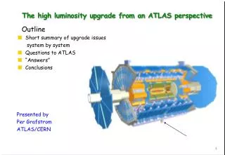
The ATLAS detector 4 Superconducting magnets: Central Solenoid (B= 2T) 3 Air core Toroids HAD calorimetry (|η|<5): segmentation, hermeticity Fe/scintillator Tiles (central), Cu/W-LAr (fwd) Trigger and measurement of jets and missing ET E-resolution: σ/E ~ 50%/√E ⊕ 0.03 Muon Spectrometer (|η|<2.7) Muon trigger and measurement with momentum resolution < 10% up to Pμ ~ 1 TeV EM calorimeter: Pb-LAr Accordion e/γ trigger, identification and measurement E-resolution: σ/E ~ 10%/√E InnerDetector (|η|<2.5, B=2T): Si Pixels, Si Strips & Transition Radiation detector tracking and vertexing, e/π separation, dE/dX Momentum resolution: σ/pT ~ 3.8x10⁻⁴ pT (GeV) ⊕ 0.015
Forward detectors B. Di Girolamo
Data Taking Efficiency the luminosity delivered (between the declaration of stable beams and the LHC request to turn the sensitive detectors off) Efficiency = --------------------------------------------------------------------------------- the luminosity recorded by ATLAS
Luminosity • The maximum instantaneous luminosity: 3.65x1033 cm-2 s-1 • Delivered Luminosity: 5.61 fb-1 • ATLAS Ready Recorded: 5.25 fb-1 Absolute luminosity calibration by van der Meer scans ΔL/L = ±3.4% (2010, prel) ΔL/L = ±3.7% (2011, prel)
Pile-up • 50 ns bunch trains for ~all 2011 data • Substantial in- and out-of-time pileup • Much progress understanding impact on performance, with data & simulation Z→μμ event with 11 primary vertices
Trigger Level-1: Implemented in hardware Muon + Calo based coarse granularity e/γ, μ, π, τ, jet candidate selection Define regions of interest (ROIs) Typical rates L1: 60 kHz L2: 5 kHz EF: 200-400 Hz Level-2: Implemented in software Seeded by level-1 ROIs, full granularity Inner Detector – Calo track matching Event Filter: Implemented in software Offline-like algorithms for physics signatures Refine LV2 decision Full event building L.Mapelli
Inner detector • Tasks: • Precision tracking covering over 5 units in eta • Primary vertex reconstruction • b-tagging • reconstruction electrons and converted photons, • electron identification with TRT • tracking of muons combined with toroidMuon Spectrometer • V0, b- and c-hadron reconstruction, ... • dE/dx from T.o.T. in Pixels and TRT • fast tracking for high level trigger
ID Performance • Reconstruction, pT resolution The inner tracking system measures charged particle tracks at all over η < 2.5 using the pixel, SCT and TRT detectors. A pattern recognition “inside-out (silicon→ TRT) tracking procedure selects track candidates with pt >100 MeV . One further step (TRT → silicon) selects tracks from secondary interactions with pt >300 MeV. • Material studies • γ-conversion • hadronic interactions • Very detailed description • Detector alignment • small residual misalignment • error scaling to allow for residual misalignments in fit Z → μμ from the Inner Detector MC: Ideal alignment Black: spring 2011 alignment Red: updated alignment Residuals of the SCT barrel modules
ID Performance Particle identification • Energy loss in Pixel • TRT High Threshold hit fraction provides electron/hadron discrimination over the momentum range between 1 and 150 GeV/c • Time over Threshold (ToT) is sensitive to dE/dx of charged particle, allowing an independent method of particle identification.
B-tagging The b-tag efficiency and mistag rate of b-tagging algorithms have been measured with a number of complementary methods using data from the ATLAS detector. Good consistency is observed between the results of all methods. This jet has all the characteristics of a b-jet with a semi-leptonic decay (to a muon). Muon Tagger:A combined muon with the following properties: • MuonpT = 6 GeV • Muon d0 = 610 microns • Muon d0/sigma(d0) = 15 • The muon is part of the secondary vertex.
Jet reconstruction • Anti-kT algorithm with resolution parameter R=0.4 – 1.2 • reconstruct jets with simple cone-like geometrical shape from calorimeter clusters or charged particle tracks • Infrared and co-linear safe • Due to the non-compensating nature of the calorimeter, signal losses due to noise thresholds and in dead material the jet energy needs to be calibrated. • Jet energy calibration is validated in-situ by: • direct transverse momentum balance between a jet and a photon • response to single isolated hadrons • multi-jet balance technique • For jet transverse momenta between 60 and 800 GeV the uncertainty is below 2.5%. Jet response as determined by the direct pT balance technique Jet energy scale uncertainty as a function of p jetT in 0 ≤ |η| < 1.2
Jet pT resolutionETmiss resolution Jet pT resolution for QCD jets was measured by Jet pT balance method. For pT ~ 1 TeVσ(pT )/ pT = 6% Fractional jet energy resolution as a function of the average jet transverse momenta for events with two jet in the same rapidity bin for EM+JES calibration with 2011 (red) and 2011 (black) data. Corrections for jet pT offset from pile-up is about 0.5 GeV/additional vertex • Exmiss and Eymiss resolution as a function of the total transverse energy was measured in minibias events as well as in the events with W(lν) or Z(ll). σ(Eтmiss ) = 0.48 √ ΣETmiss
Tau-lepton • Tau leptons are recognized in the ATLAS detector via their hadronic decays. • Tau leptons versus QCD jets: • number of final state particles • width of the energy depositions in the calorimeter • displacement of the secondary vertex • small invariant mass • The tau identification efficiency has been measured in data using W→τν and Z →ττ events • The tau energy scale is obtained from the measured transverse momentum by scaling it to its expected value from Monte Carlo simulation of tau decays. • Systematic uncertainty on the tau energy scale ~2% Inverse background efficiency (in dijet data) versus signal efficiency (in W->τν and Z->ττ Monte Carlo samples)
e/γ Electron identification • Three reference sets of requirements provide progressively stronger jet rejection : • Loose: shower shape in the second layer of the EM calorimeter and energy leakage into the hadronic calorimeters. • Medium: the energy deposit patterns in the first layer , track quality variables, distance to the primary vertex and a cluster-track matching • Tight: the ratio of cluster energy to track momentum, the number of hits in the TRT, the ratio of high-threshold hits to the total number of hits in the TRT, at least one hit in the first layer. MC efficiency and resolution agreed with data
Photon identificationEnergy and mγγresolution π0 candidate ϒ candidate loose and tight selections optimized separately for unconverted and converted γ Isolation: ETiso<3 GeV γ shower Examples of discriminating shower shape variables transverse shape variable energy deposit in the first longitudinal compartment of the electromagnetic calorimeter Surrounding ET Eγ and Mγγ resolution is estimated with Monte-Carlo. The core component of the massresolution ranges from 1.4 GeV in the “Unconverted central” category to 2.1 GeV in the “Converted transition” category. Monte-Carlo for H→γγ MH = 120 GeV
Muon combined The momentum resolution is extracted from the width of the di-muon mass distribution in Z →μμ decays and the comparison of the independent measurements of muons from Z →μμ and W →μν decays provided by the two ATLAS tracking systems, the Inner Detector and Muon Spectrometer. The muon reconstruction efficiencies are measured with Z →μ+μ− decays in which one of the decay muons is reconstructed in both systems and the other is identified by just one of the systems in order to probe the efficiency of the other.
LHC plans Aim to produce ~3000 fb-1delivered to the experiments over 10 years.
ATLASWhy upgrade? • LHC luminosity goes beyond the nominal luminosity • New technologies → better detectors • Experience with ATLAS → better understanding of needs and opportunities • Aging
Tentative time schedule • The multi-phase detector upgrade: Phase 0, I, II • 2010-2012 Run 1: √s = 7 TeV (2012: 8-9 TeV ?) , L = 3 x 1033 cm-2s-1 • 2013-2014 Shutdown. Phase 0: • Detector consolidation • New pixel layer • 2014-2017 Run 2: √s = 14 TeV, L = 1 x 1034 cm-2s-1 • 2018 Shutdown. Phase 1: • Small muon wheels • Trigger upgrade • 2019-2022 Run 3: √s = 14 TeV, L = 2 x 1034 cm-2s-1 • 2022 Shutdown. Phase 2 • New inner tracker • Warm forward calorimeter • New muon chambers • Trigger upgrade • 2023-2030? Run 4: √s = 14 TeV, L = 5 x 1034 cm-2s-1
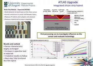
Phase 0 • Consolidation: • New beam pipe (steel → Al, Be → Be): reduction of background in cavern • Complete installation of EE muon chambers • New LV power for LiArgon • New LV power for TileCal • Repairing Installation of new pixel layer ATLAS TDR 19, CERN/LHCC 2010-013
Phase 0Insertable B-Layer • Pixel (n+-on-n sensor) : • 3 barrels + 2x3 discs (5 < R < 15cm) • Strip (SCT) (p+-on-n sensor) : • 4 layers + 2x9 discs (30 < R < 51cm) • TRT (straw drift tubes) : • Barrel + Wheel (55 < R < 105cm) • Plan: • Exchange beampipe with thinner one • Use additional space for a 4th pixel layer: • Insertable B-Layer (IBL) Designed for fluences of : • Pixel B-layer : 1 x 10¹⁵ 1MeV neq/cm2 • SCT layer 1 : 2 x 10¹⁴ 1MeV neq /cm2 • TRT outer rad : 3 x 10¹³ 1MeV neq/cm2
IBL 25 • The IBL fulfils several functions: • improved determination of secondary • vertices → better b-tagging • 'hot spare' for existing b-layer • 4th pixel hit → improved tracking • Challenges: • New sensors • New readout • Material budget • Space budget
IBL readout • Current readout chip FE-I3 • inefficient beyond 3 ∙ 1034 cm-2 s-1 • New chip FE-I4 assets: • local memory cells • larger active fraction • higher data rate • more radiation hard (130 nm) FE-I3 FE-I4 Pixel Size [μm2] 50×400 50×250 Pixel Array 18×160 80×336 Chip Size [mm2] 7.6×10.8 20.2×19. Active Fraction 74 % 89 %
IBL performance Event with 2 jets of 500 GeV tracks pT > 0.5 GeV and # cluster > 1 Pixel+IBL same event adding pileup for L=2x1034cm-2s-1 same track selection applied Resolution in x of the reconstructed primary vertex without beam spot constraint for t t̄ events with and without the IBL Efficiency for reconstructing the primary vertex in t t̄ events with and without the IBL
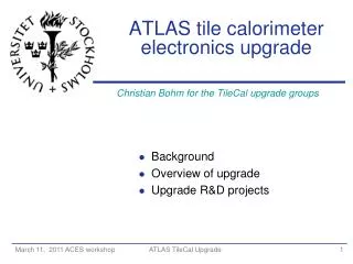
Muon chambers (EE) Complete installation of EE muon chambers These chambers improve momentum resolution at 1<η<1.4 Pt = 100 GeV/c.
L1 mu rate dominated • by endcap • L1MU20 rate • extrapolation to 1x1034 • 10 kHz at 7 TeV • 20 kHz (?) at 14 TeV • 60 kHz at 3x1034 Phase 1Small wheels • removing background • • improving pT resolution New small wheels for phase-1: • precision tracker with high rate capability • fast segment reconstruction for L1 upgrade Present muon L1 MDT • Based on EM (Big wheel) • segments: • many background tracks • fake high pTmuons CSC TGC Upgrade Integrate EI (Small wheel) segments in trigger: requiring an IP pointing segment on EI matched to the EM segment T. Kawamoto
The small wheels options sMDT + sTGC sMDT : 15 mm tube instead of 30 mm ( x7 increase of rate capability) sTGC : strip readout for precision coordinates (~100 μ) for 1 mrad resolution sMDT + mRPC mRPC : 2x1 mm gap instead of a single 2 mm gap combined with low noise amplifier big reduction of charge high rate, long life Micromegas Based on a single technology for both tracking and trigger Very high rate capability, good position resolution New’technology for the use in large scale (~ 1 m size) T. Kawamoto
The Fast TracKer (FTK) • FTK is a hardware track finder up to 3 orders of magnitude faster than L2 processor farm • Technical Proposal April 13, 2010 • frees L2 farm time • could scale to 1035 cm-2 s-1 • track parameters comparable to offine • tracking • off-detector → upgrade without long access • will not reduce L1 trigger rate but help at L2 • template technology interesting for SLHC global tracking in two steps: pattern recognition and track fit
Challenges: • Charge build-up in Liquid Argon gap • Higher current draw → HV drop • High ionization load → Lar boiling Forward calorimeter Baseline: small warm calorimeter in front of the LAr FCAL in order to protect it from heating, ion build-up Copper absorbers +1 cm2 diamond sensors on ceramic highly segmented readout Options: Warm High-pressure Xe LAr mini-Fcal • Or: • Replace FCal with super FCal (sFCal) • Smaller gaps • New HV protection resistors • Additional cooling Phase 1 – Phase 2 ? Simulation results on the energy deposited on FCal1. Will cold electronics inside end-cap survive 3000 fb-1?
The ATLAS Forward Physics Project (AFP) • ~210 m from ATLAS IP consisting of 3 main parts • Movable Beam Pipe • Si Detectors (momentum) • Timing (backgrounds) Si Detectors: Baseline: - IBL 3D Si sensors; dead edge ~225 μm Very promising R&D for edgeless/active-edge 3D Si; dead edge ≤50 μm. - FE-I4b Readout chips, • Timing detectors • Crucial to reduce backgrounds from • ≥2 single-diffraction events in same crossing • Baseline: • -quartz bars • -MCP-PMT To be approved
Phase 2 Trigger • More processing at L1 : • • sharpening threshold for leptons and calorimeter energy • full readout of digitized energy from all cells over high speed optical link • bringing higher granularity for L1 calorimeter trigger • L1Track? • Longer L1 latency : • 3μs → 6μs or 9μs or even longer
Inner tracker Rate : • Pixel B-layers will become inefficient at 2x1034 • SCT (strip), bandwidth limitation • TRT occupancy will become very high Radiation damage: • SCT designed for 700 fb-1 • Much shorter life for B-layer I. Dawson • All new inner tracker for Phase2 • • higher granularity to keep occupancy low • improved radiation hardness • • improved material budget • • baseline : all silicon strip + pixel A.Zalzburger
Inner tracker All silicon: pixel (4 layers), short strips (3.5 cm, 3 layers), long strips (9 cm, 2 layers) 40M channels in Si strips (6M in the current detector) 160M channels in Si pixel (80M in the current detector) n-in-p sensors in full size available Breakdown voltage > 1000 V Radiation hardness verified up to 1015neq cm-2
Muon detectors • More shielding • New/additional muon chambers Limitation of the present MDT : 200-300 kHz/tube
Conclusion 1 fb-1 → 3000 fb-1 0.03% → 100%
Data analysis Grid: A distributed computing infrastructure, uniting resources of HEP institutes around the world to provide institutes seamless access to CPU and storage for the LHC experiments • Tier-0 (CERN) : recording –reconstruction –distribution • Tier-1 (~10 centres) : storage -reprocessing –analysis • Tier-2 (~140 centres) : simulation –end-user analysis
Aplanarity: the smallest eigenvalue of the momentum tensor • HT;3p : the transverse momentum of all but the two leading jets, normalized to the sum of absolute values of all longitudinal momenta in the event • The anti-kt algorithm constructs, for each input object (either energy cluster or particle) i, the quantities dijand diB as follows: where kti is the transverse momentum of object i with respect to the beam direction. A list containing all the dij and diB values is compiled. If the smallest entry is a dij, objects i and j are combined (their four-vectors are added) and the list is updated. If the smallest entry is a diB, this object is considered a complete ‘‘jet’’ and is removed from the list.