Download
1 / 23
230 likes | 332 Views
Phase Diagrams Quick Review of Linear Oscillator (Ch.3). Consider a 1d Linear Oscillator: Its state of motion is completely specified if two quantities are given at the initial time t 0 : x(t 0 ), v(t 0 ) = x(t 0 ) .

E N D
Phase DiagramsQuick Review of Linear Oscillator (Ch.3) • Consider a 1d Linear Oscillator: Its state of motion is completely specified if two quantities are given at the initial time t0: x(t0), v(t0) = x(t0). • 2 quantities because Newton’s 2nd Law is a 2nd order differential equation in time! Its useful to consider x(t) & x(t) = v(t) as coordinates in a 2d phase space. • For a 3d particle, the phase space would be 6 dimensional! • At any time t, the 1d oscillator motion is completely specified by specifying a point in this 2d phase space(x - v or x - x plane).
At time t, the oscillator motion is specified by specifying point P = P(x,x). As t progresses, P will move in this plane & trace out a Phase Path / Phase Trajectory. • Different initial conditions Different phase paths • The totality of all possible phase paths of the particle Phase Portrait / Phase Diagram of the particle. Studying such diagrams gives insight into the physics of the particle motion. • This is not limited to oscillators, of course, but clearly is a valid concept for any particle!
Look in detail at the phase diagram for the 1d simple harmonic oscillator: x(t) = A sin(ω0t - δ) v(t) = x(t) = ω0A cos(ω0t - δ) • Eliminating t from these 2 eqtns gives: [x2/A2] + [x2/(A2ω02)] = 1 • This is a family of ellipses in the x - x plane! • The phase diagram for the 1d oscillator = a family of ellipses, each of which is a separate phase path, for different initial conditions.
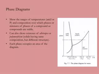
The phase diagram for the 1d oscillator is a family of ellipses, as in the Figure. • Note: Oscillator total energy: E= (½)kA2. Also, ω02 = (k/m) The ellipse equation can be written: [x2/(2E/k)] + [x2/(2E/m)] = 1
Writing the elliptical phase path as [x2/(2E/k)] + [x2/(2E/m)] = 1 PHYSICS: Each phase path (ellipse) corresponds to a definite total energy of the oscillator (different initial conditions!). No 2 phase paths of the oscillator can cross! • If they could cross, this would mean that for given initial conditions x(t0), v(t0), the motion could proceed on different phase paths. This is impossible, since the solutions to a linear 2nd Law differential equation are unique!
In constructing a phase diagram: Choose x as the “x-axis” & x = v as the “y-axis”. • The motion of a typical point P(x,x) is always clockwise! Because, for a harmonic oscillator, for x > 0, x = v decreases & if x < 0, x = v increases! • Earlier we obtained x(t) = A sin(ω0t - δ) & v(t) = x(t) = ω0A cos(ω0t - δ) by integrating N’s 2nd Law Eq. (a 2nd order differential equation): (d2x/dt2)+ (ω0)2x = 0 • But, we can get the phase path in a simpler way.
Phase Diagram with Damping • Underdamped linear oscillator:A spiral phase path. A continually decreasing magnitude of the radius vector to the origin in the x-v plane is an indication of damped oscillations.
Phase Diagrams for Nonlinear Systems Section 4.3 • At first, consider only conservative systems(so U(x) is defined). General Method to Construct a Phase Diagram Use energy conservation! E = (½)mv2 + U(x) = (½)mx2 + U(x) (1) For fixed E, get the function x(x) or v(x) by solving (1) for v = x: v(x) = x(x) = ±[(2/m)(E -U(x))]½ (2) (2) is especially useful for nonlinear systems! Given U(x), its usually straightforward to numerically compute v(x).
We can obtain a qualitative phase diagram for a fixed energy E by noting the shape of U(x) & using: v(x) = x(x) = ± [(2/m)(E -U(x))]½ • Consider a particle confined to the potential U(x) in the figure. (Soft for x < 0. Hard for x > 0)
Assuming no damping, & using v(x) = ±[(2/m)(E -U(x))]½ we can reason that the phase diagram must be as shown here: 3 oval phase paths, corresponding to the 3 different energies E.
v(x) = ±[(2/m)(E -U(x))]½ For energy E only slightly above the minimum of U(x), the ovals approach ellipses (which, from the linear oscillator discussion, is what they would be for a parabola: Ulinear(x) = (½)kx2). This corresponds to fact (already discussed) that, near the minimum of U(x), we can approximate U(x) as a parabola (linear oscillator!).
v(x) = ±[(2/m)(E -U(x))]½ • Recall:The damped linear oscillator phase diagram is an inward spiraling path. Similarly, in thisnonlinear case, if we add damping, the ovals will spiral inward as the particle goes to the potential minimum & eventually comes to rest at x = 0. • The equilibrium point x = 0 is an example of an attractor. • ATTRACTOR A set of points (or one point) in x-v phase space towards which a system is “attracted” when damping is present.
For case just discussed, x = 0 is a position of stable equilibrium, since (d2U/dx2)0 > 0(x = 0 is a minimum). Themotion will be bounded, no matter how nonlinear F(x) is (no matter how non-parabolic U(x) is). • By contrast, now consider a particle moving near a point where U(x) has a maximum(say x = 0, as in the figure). In this case, x = 0 is a position of unstable equilibrium(d2U/dx2)0 < 0 For a particle at rest there, a slight disturbance will cause it to “roll downhill”.That is, themotion will be unbounded.
Figure: Consider an asymmetric U(x) with maximum at x = 0 • A particle at energies E0, E1, E2 would have unbounded motion. To understand the phase diagram (below):Imagine first the case where, instead of the one in the figure, U(x) is an “upside down” parabola: U(x) = - (½)kx2. In that case,the phase paths with energy E0would be straight lines & those with energies E1, E2 would be hyperbolas. The phase paths in the figure approach these in the limit as the nonlinearity in F(x) (the non-parabolicity of U(x)) goes away.
By looking at the phase diagrams for the 2 potentials we’ve discussed (“valley” & “hill”) One can (qualitatively) construct the phase diagram for an arbitraryU(x), with both “hills” & “valleys”. It would be some superposition or combination of the two phase diagrams.Near a “valley”, it looks like the one on the left, near a “hill”, it looks like the one on the right!
Van der Pol Equation • An interestingexample of a non-linear equation of motion: “The van der Pol Equation” (d2x/dt2) + μ(x2 - a2)(dx/dt) + ω02x = 0 (1) μ > 0 (usually small). Find x(t)! • The physics behind this equation? The corresponding U(x)? • Electrical oscillators in vacuum tube circuits. See footnote, p. 153. • Compare & contrast (1) with the equation of motion for the linear oscillator with damping: (d2x/dt2) + 2β(dx/dt) + ω02x = 0 (2) Comparing (1) & (2): 2β μ(x2 -a2) The Van der Pol Equation is linear oscillator with damping, but with an x dependent damping coefficient(the amount of damping depends on x = x(t), which is the unknown solution to the equation (1)!)
Van der Pol Phase Diagrams Schematic of a phase diagram (d2x/dt2) + μ(x2 - a2)(dx/dt) + ω02x = 0 • Note: If the amplitude |x(t)| exceeds a critical value |a|, thenμ(x2 - a2) > 0 & the system is damped. The x-v phase diagram is an inward spiral(towards x = a). • Note: If the amplitude |x(t)| is less than |a|, thenμ(x2 - a2) < 0 & the system is “negatively” damped! OR: x(t) increases exponentially without limit! The x-v phase diagram is anoutward spiral(towards x = a). • Note: If |x(t)| = |a|, thenμ(x2 - a2) = 0 & the system is an undamped linear oscillator. (No increase or decrease in x(t) with time). The x-v phase diagram is an ellipse. a -a
(d2x/dt2) + μ(x2 - a2)(dx/dt) + ω02x = 0 (1) • For (1), the curve |x(t)| = |a| is an ellipse in the x-v phase plane. This curve is an example of a general concept in the x-v phase plane: “Limit Cycle” A curve such that all paths outside it spiral inward & all paths inside it spiral outward. The limit cycle is also the attractor for this system. • The Limit Cycle defines locally bounded motion Therefore it also represents a stable state for this non-linear oscillator.
Van der Pol Equation (d2x/dt2) + μ(x2 - a2)(dx/dt) + ω02x = 0 (1) • A system which obeys the Van der Pol Equation is an example of a system which isSELF-LIMITING. • Once the oscillator is set into motion under initial conditions which lead to increasing amplitude |x(t)| < |a| so that μ(x2 -a2) < 0, the amplitude isprevented from growingwithout bound. • In this case, there is a maximum (limiting) amplitude = |a| • Once it is set into motion under initial conditions which lead to decreasing amplitude |x(t)| > |a| so that μ(x2 -a2) > 0 the amplitude isprevented from decreasingto zero. • In this case, there is a minimum (limiting) amplitude = |a|
Numerical Solution of the Van der Pol Eqtn (d2x/dt2) + μ(x2 - a2)(dx/dt) + ω02x = 0 (1) • Note: The following differs from your text, which I think has the wrong explanation to go with the figures they generated! To make the numerics easier, choose a system of units where a = 2, ω02 = 1 (text says a = 1?) (1) becomes: (d2x/dt2) + μ(x2 - 4)(dx/dt) + x = 0 (2) • The limit cycle is an ellipse semimajor axis 2. The authors solve this on a computer (using Mathcad) using μ = 0.05 (small damping) It will take a long time for x to reach the limit cycle |x| = |a| = 2. Look at it for 2 different initial conditions: x(0) = 1.0 (< a = 2) & x(0) = 3.0 (> a = 2). In both cases, x(0) = v(0) = 0.
(d2x/dt2) + μ(x2 - 4)(dx/dt) + x = 0 (2) • Limit cycle = ellipse semimajor axis = 2. μ = 0.05 2 initial conditions: x(0) = 1.0 (< a = 2) x(0) = 3.0 (> a = 2) v(0) = 0. Solutions in the figure Both cases: Clearly the solution spirals towards the limit cycle for long times. In this small damping case, x(t) & v(t) are both sinusoidal in time for long times.
(d2x/dt2) + μ(x2 - 4)(dx/dt) + x = 0 (2) • Limit cycle = ellipse semimajor axis = 2.μ = 0.5 (large damping) 2 initial conditions: x(0) = 1.0 (< a = 2) x(0) = 3.0 (> a = 2) v(0) = 0. Solutions in the figure Both cases: The solution spirals towards the limit cycle much more quickly than in the other case. In this large damping case, x(t) & v(t) are skewed from being sinusoidal in time for long times.