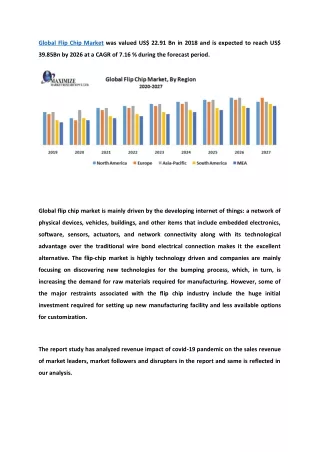
Flip Chip Technology
Flip Chip Technology. Microwave Device Term Project. 2005/6/16 Kim Dong Hwan School of Electrical Engineering and Computer Science Seoul National University, Korea. Contents. Introduction Wire Bonding vs. Flip Chip interconnect Flip Chip Process (SSB & MSB) Conclusion. Introduction.

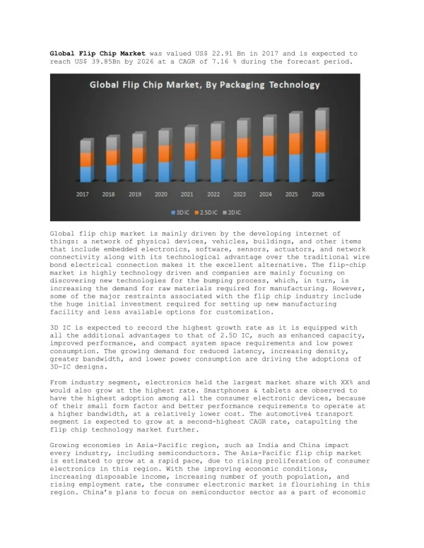
Flip Chip Technology
E N D
Presentation Transcript
Flip Chip Technology Microwave Device Term Project 2005/6/16 Kim Dong Hwan School of Electrical Engineering and Computer Science Seoul National University, Korea
Contents • Introduction • Wire Bonding vs. Flip Chip interconnect • Flip Chip Process (SSB & MSB) • Conclusion
Introduction • Advancements in the packaging of semiconductor devicestraditionally use wire bonds to provide the interconnect from device to substrate or to other devices • Along with the rapid advances in microwave and millimeter wave subsystem development a growing interest concerning chip interconnectiontechniques has developed. • The importance of quality of these interconnects a large impact on the performance of the entire subsystem, especially at high frequencies. • Flip chip offers advantages over traditional interconnect schemes. A smaller overall footprints, better thermal heat transfer
Introduction • Wire Bonding vs. Flip Chip interconnect • Flip Chip Process (SSB & MSB) • Conclusion
Wire Bonding Wire length loss Bond ribbon [Coplanar Waveguide Model]
Flip Chip Interconnection MMIC(2mm 50 CPW line) CPW Motherboard on 20-cm Si wafer Bump Compared to the Bond Wire Small Big [Flip Chip Interconnection of Coplanar MMIC] [EM-Simulation Structure for RF test] [Gold(Stud) Bumps attached] Ref.Songsub Song
Flip Chip Interconnection Bump Height ≥ Spacing ☞ The influence of substrate surface -> negligible {Bump height ≥ Ground to ground spacing of the transmission lines}
Flip Chip Interconnection Flip Chip Interconnection Versus Wire Bonding Insertion loss Return loss Beyond 100GHz → Below 0.5dB
50 CPW (D= 80mm) • Alumina substrate MMIC or Device MMIC or Device Change in Z0 ( % ) ~ 3 % change at 20 mm D D Motherboard Motherboard Air gap (mm) [ E-field distribution for a flip-chip mounted CPW MMIC ] [ E-field distribution for a flip-chip mounted CPW MMIC ] [ Change rate of characteristic impedance as a function of air-gap for a flip-chip mounted CPW MMIC ] Proximity Effect in Flip-Chip Structure Height of flip-chip bump (air-gap) Ref. Sangsub Song, “The Flip-Chip Mounted MMIC Technology using the Modified MCM-D Substrate for Compact and Low-Cost W-band Transceivers”
Why Flip Chip Technology? CPW MMIC m-strip MMIC Wire -Bonding Ground Via Flip-Chip Bump 50 ~ 100 mm [ Flip-Chip Bonding Technology ] [ Wire-Bonding Technology ] ~ 650 mm Advantages of Flip Chip Bonging Technology. Short Interconnection Length Better Electrical Performances High reproducibility High Yield & Less Tuning Compact size High Packaging density Passive components are made in dielectric substrate such as alumina Ceramics, SiO2 and BCB Low Cost
Introduction • Wire Bonding vs. Flip Chip interconnect • Flip Chip Process (SSB & MSB) • Conclusion
Stud Bump Bonding Technology [Cross-sectional SEM photograph of the bonding portion by SBB] [Process flow of the SBB]
Micro Bump Bonding Technology -To cure the resin [Cross-sectional SEM photograph of the bonding portion by MBB] [Process flow of the MBB] ☞ Further requirements for miniaturization and higher frequency operation
Conclusion • The need for smaller packaging • Flip chip interconnect process → more compact fashion • Improved electrical performance • Reduced interconnect length → lower inductance and reduced signal loss → lower power requirements • The demands of high frequency applications • Limitation of the wire interconnect → flip-chip bump connection [Flip Chip Bump Connection] [Wire connection]
References [1] Mark S. Hauhe, “Flip Chip Technology Vendor Overview,” [2] R. Sturdivant, “Reducing the effects of the mounting substrate on the performance of GaAs MMIC flip chips,” in Proc. 1995 Int. Microwave Theory Tech. Symp. Dig., Orlando, FL, May 1995, pp. 1591-1594. [3] Hideki Kusamitsu, et al., “The Flip-Chip Bump Interconnection for Millimeter Wave GaAs MMIC,” IEEE Transactions on Electronics Packaging Manufact- uring, VOL. 22, NO .1, January 1999. [4] T. Krems, et al., “Millimeter-Wave Performance of Chip Interconnections Using Wire Bonding and Flip Chip,” IEEE MTT-S Digest. pp. 247-250. [5] Hiroyuki Sakai., “High Frequency Flip-Chip Bonding Technologies and Their Application to Microwave/Millimeter-wave ICs,” IEICE TRANS. Electron., VOL. E81-C, NO. 6 June 1998. [6] Kiyomitsu Onodera, et al., “Novel Flip-Chip Bonding Technology for W-Band Interconnections Using Alternate Lead-Free Solder Bumps,” IEEE Microwave and Wireless Components Letters, VOL.12, NO. 10, October 2002. [7] Sangsub Song, “The Flip-Chip Mounted MMIC Technology using the Modified MCM-D Substrate for Compact and Low-Cost W-band Transceivers” IEEE IMS 2005. Microwave Application Seminars.