Experience with C4 flip-chip
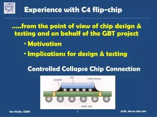
Experience with C4 flip-chip. …..from the point of view of chip design & testing and o n behalf of the GBT project Motivation Implications for design & testing Controlled Collapse Chip Connection. Motivation: GBT-SERDES (prototype GBTX). dOut [29:0]. DES. Digital Core. Parallel

Experience with C4 flip-chip
E N D
Presentation Transcript
Experience with C4 flip-chip • …..from the point of view of chip design & testing and on behalf of the GBT project • Motivation • Implications for design & testing • Controlled Collapse Chip Connection ACES, March 10th 2011
Motivation: GBT-SERDES (prototype GBTX) dOut [29:0] DES Digital Core Parallel Out/ BERT rxDataValid 120 120 Serialinput rxClock40 rxClock160 4.8 Gbit/s serial data More details from Paulo Moreira today Phase Shifter ClkOut3 60-bit I/O bus at 160 MHz …….. 169 pads (but many more for GBTX) ClkOut2 ClkOut1 ClkOut0 Clock Generator Clockreference rxRdy Control Logic txRdy I2C JTAG AUX[n:0] RST SER dIn [29:0] Parallel In/ PRBS 120 txDataValid Serial out 120 txClock40 txClock160 PROMPT Power On RESET reset ACES, March 10th 2011
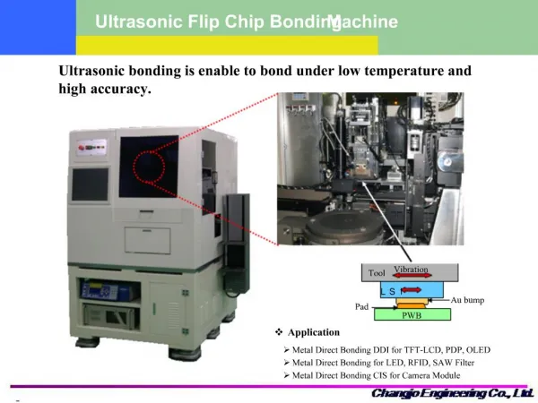
Motivation: GBT-SERDES (prototype GBTX) • High speed lines: minimise inductance • Direct powering to blocks • Direct cooling on back-side (although coverplate is material eg Cu) • Die size is pad-limited; extra silicon (400 I/Os in GBTX) • Mount on BGA package ACES, March 10th 2011
Technical Information IBM 130nm library - C4 pad only in LM metal stack - pad & drivers separate blocks IBM deposit bumps on wafers; - more masks => extra cost - MPWs: split between C4 & wirebond Size/pitch = “5 on 10” IBM standard (recommended for yield) = 125/250mm Package vendor recommended High-Temperature Solder (97Pb3Sn) for reliability 146mm ACES, March 10th 2011
Design Implications Floorplan at start of design Communicate early with package/hybrid designers -> we iterated a few times -> placement of signal/power pads Routing by hand is difficult -> we used the CERN-VCAD ‘digital design flow’ (analog blocks incorporated as black-box abstracts) Solve ALL DRCs (even if not physical!) ACES, March 10th 2011
Layout & Bumped Die ACES, March 10th 2011
Testing Results Package designed by Endicott Interconnect Assembly by Endicott No cover-plate mounted No C4 problems found on chips tested so far Chip testing issues: Need complex package/hybrid immediately Package design was significant part of project cost Chip orientation is bad for radiation testing attenuation of 10keV X-rays in CERN facility back-grinding needed for heavy ion tests ACES, March 10th 2011
Summary C4 has many performance advantages Standard industrial process Requires careful planning: floorplan, package/hybrid Implies extra financial cost upfront Extra cost may be offset by savings elsewhere ACES, March 10th 2011