Download
1 / 17
170 likes | 344 Views
Overview of the RFCC Module and 201-MHz Cavity Design. Derun Li Lawrence Berkeley National Laboratory. RFCC Module RF Cavity Design Review October 21, 2008. Outline. Introduction of RFCC module of MICE cooling channel and charge of the review Review of the 201-MHz cavity design

E N D
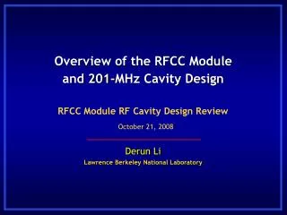
Overview of the RFCC Module and 201-MHz Cavity Design Derun Li Lawrence Berkeley National Laboratory RFCC Module RF Cavity Design Review October 21, 2008
Outline • Introduction of RFCC module of MICE cooling channel and charge of the review • Review of the 201-MHz cavity design • MuCool 201-MHz prototype cavity: baseline design for MICE • Physics design and cavity fabrications • Cavity body • RF coupler • Be windows • Tuners • Recent progress • Vendor identification • Engineering CAD model and FEA analysis • Tuners and cavity support • Integration and interface • Schedule Derun Li - Lawrence Berkeley National Lab - October 21, 2008
Eight 201-MHz Cavities for MICE Eight201-MHz RF cavities MICE Cooling Channel Courtesy of S. Q. Yang, Oxford Univ. RFCC modules Derun Li - Lawrence Berkeley National Lab - October 21, 2008
SC coupling Coil Curved Be window Cavity Couplers Vacuum Pump 201-MHz cavity RFCC Module Derun Li - Lawrence Berkeley National Lab - October 21, 2008
Charge of this Review • Evaluate the engineering design of RFCC module and the RF cavity • Evaluate engineering design and fabrication schemes of the 201-MHz cavity • Spinning of cavity shells • e-beam welding • Port extruding • Tuners • Cavity support • Cavity assembly • Evaluate overall module concept • Interface with other modules • Site interfaces • Integration and shipping • Detailed design of CC is not part of this review • CC design review scheduled: Dec. 6-8, 2008 at ICST of HIT, Harbin Derun Li - Lawrence Berkeley National Lab - October 21, 2008
RFCC & Cavity Design Review Agenda • 15:300 – 18:30 October 21, 2008 at RAL • Overview of RFCC Module and Recent Progress Li • 201 MHz Cavity Fabrication Plan DeMello • Assembly, Installation and Interface Virostek • Coffee break • RFCC Module and Subcomponents Mechanical Design DeMello • Schedule and Manpower Virostek • Discussion • Executive Session Committee • Closeout Derun Li - Lawrence Berkeley National Lab - October 21, 2008
MICE RF Cavity Summary • MICE RF cavity design is based on the successful prototype cavity for the US MuCool program • Fabrication of the prototype cavity was successful • A slight reduction in cavity diameter to raise the frequency has been specified and analyzed • The fabrication techniques used to produce the prototype will be used to fabricate the MICE RF cavities • Preliminary cavity design was reviewed at CM21 at DL • Copper sheets have been ordered and expected to arrive mid-December 2008 • A detailed WBS schedule for the design and fabrication of the MICE RF cavities has been developed Derun Li - Lawrence Berkeley National Lab - October 21, 2008
MICE RF Cavity Design • 3-D Microwave Studio RF parameterized model including ports and curved Be windows to simulate frequency, Epeak, etc. • Hard to reach the design frequency by spinning technique • Frequencies between cavities should be able to achieve within 100 kHz • Approaches • Modification the prototype spinning form • Targeting for higher frequency • Fixed tuner to tune cavity close to design frequency (deformation of cavity body) • Tuners are in push-in mode lower frequency Derun Li - Lawrence Berkeley National Lab - October 21, 2008
Cavity Design Parameters • The cavity design parameters • Frequency: 201.25 MHz • β = 0.87 • Shunt impedance (VT2/P): ~ 22 MΩ/m • Quality factor (Q0): ~ 53,500 • Be window diameter and thickness: 42-cm and 0.38-mm • Nominal parameters for MICE and cooling channels in a neutrino factory • 8 MV/m (~16 MV/m) peak accelerating field • Peak input RF power: 1 MW (~4.6 MW) per cavity • Average power dissipation per cavity: 1 kW (~8.4 kW) • Average power dissipation per Be window: 12 watts (~100 watts) Derun Li - Lawrence Berkeley National Lab - October 21, 2008
201 MHz Cavity Concept Spinning of half shells using thin copper sheets and e-beam welding to join the shells; extruding of four ports; each cavity has two pre-curved Beryllium windows, but also accommodates different windows Derun Li - Lawrence Berkeley National Lab - October 21, 2008
RF Cavity Fabrication Overview The same fabrication techniques used to make the prototype cavity will be used for the MICE RF cavities Engineering CAD Model of the RF Cavity • Cavity half-shells to be formed by metal spinning • Precision milling of large parts (1.2 m diameter) • Precision turning of mid-sized parts (0.6 m dia.) • Precision manufacture of smaller parts • CMM measurements throughout the process • To limit any annealing and maintain cavity strength, e-beam welding will be used for all cavity welding • cavity equator, stiffener rings, nose rings, port annealing and port flanges • Cavity inside surfaces are finished by electro-polishing Prototype RF Cavity Derun Li - Lawrence Berkeley National Lab - October 21, 2008
Progress Summary RF Cavities • Material to arrive 12/08 • Fabrication steps identified • RF, thermal, structural analyses done • Detailed design complete • Fabrication drawings nearly done • Vendor qualification under way • Be windows being ordered • Final vendor selection not complete • Electropolish not fully defined Cavity tuners • RF, structural analyses complete • Actuation cylinder type identified • Detailed design, drawings not complete Derun Li - Lawrence Berkeley National Lab - October 21, 2008
Progress Summary (cont.) Cavity Struts • Structural analysis complete • LBNL standard detailed design • Fabrication, installation dwgs not done Coupling Coil Interface • Magnet gusset mod sent to ICST • Additional interface details TBD Cavity Cooling Water • Feedthrough concept developed • Detailed design not complete Derun Li - Lawrence Berkeley National Lab - October 21, 2008
Progress Summary (cont.) Module Vacuum Vessel • Conceptual design/CAD model complete • Structural analysis not complete • Detailed design, drawings not complete Module Vacuum System • Conceptual design complete • Lumped parameter analysis soon • Failure analysis not complete • Detailed design, drawings not complete RF Couplers • Design previously developed for MuCool cavity • Modifications for MICE not complete • Detailed design, drawings not complete vacuum Derun Li - Lawrence Berkeley National Lab - October 21, 2008
Progress: Other Module Components Cavity Suspension Dynamic Tuners RF Coupler Beryllium Window Vacuum System Module Support DeMello’s talk for more details Derun Li - Lawrence Berkeley National Lab - October 21, 2008
Liquid Nitrogen Cooling Considerations • Suspension of cavities on struts provides low heat leak from cavity to vacuum vessel • Beryllium window FEA thermal analysis will need to be performed with new parameters • The cavity frequency will be shifted (approximately 600 kHz), therefore tuning system or RF power source modifications will be needed • Insulators will need to be added to the RF couplers • Coaxial LN feedthrough tubes will be needed to insulate the connection outside of vacuum Derun Li - Lawrence Berkeley National Lab - October 21, 2008
Summary • Good progress since last CM and review, details of technical designs, interface and schedules (DeMello and Virostek) • Responses to last review (DeMello) • RFCC & Cavity Design Review Agenda • (15:30 – 18:30 October 21, 2008 at RAL) • Overview of RFCC Module and Recent Progress Li • 201 MHz Cavity Fabrication Plan DeMello • Assembly, Installation and Interface Virostek • Coffee break • RFCC Module and Subcomponents Mechanical Design DeMello • Schedule and Manpower Virostek • Discussion • Executive Session Committee • Closeout Derun Li - Lawrence Berkeley National Lab - October 21, 2008