Download
1 / 27
270 likes | 374 Views
This project focuses on developing a high-power target for the J-PARC Neutrino Project, aiming to enhance beam power for future accelerators. The target station design includes elements like the target window, horns, decay pipe, and waste storage area. The target material needs to withstand thermal shock and have a high melting point. The size and properties of the target are crucial for efficient focusing of pions to generate neutrinos. Cooling systems, such as water cooling, are considered to maintain target temperature below the melting point. Experimental tests and calculations have been conducted to determine heat transfer rates and optimize cooling efficiency for the target.

E N D
The JPARC neutrino target KEK Yoshinari Hayato (For J-PARC target/monitor Group) High-power targetry for future accelerators Ronkonkoma, NY.
Conventional beam Next generation LBL experiments in Japan“J-PARC - Kamioka neutrino project” Baseline ~295km Beam Energy ~1GeV Will be adjusted to the oscillation maximum Beam power Physics Far detector disappearance Super Kamiokande(50kt) appearance 0.75MW NC measurements
J-PARC facility N JAERI@Tokai-mura (60km N.E. of KEK) Neutrino Beam Line Construction 2001~2006 JFY 3GeV PS 400MeV Linac (Approved in Dec.2000) 50GeV PS (0.75MW) FD To SK
JPARC neutrino beamline Primary Proton beam line Extraction point Proton beam kinetic energy 50GeV(40GeV@T=0) # of protons / pulse 3.3x10¹⁴ Target Beam power Target station 750kW Bunch structure Decay volume 8 bunches Bunch length (full width) beam dump 58ns Bunch spacing muon monitor 598ns Spill width Near neutrino detector ~5ms Cycle 3.53sec
Off Axis Beam(another NBB option) (ref.: BNL-E889 Proposal) Far Det. Target and Horns Decay Pipe q ( a few degrees) WBB w/ intentionally misaligned beam line from det. axis Decay Kinematics Quasi Monochromatic Beam
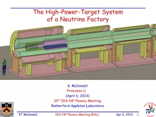
40ton crane Ground level Service pit Concrete Beam window Iron shield Machine room He container Beam window Cooling Concrete Baffle Waste storage area Target+1st horn 2nd horn 3rd horn Target station
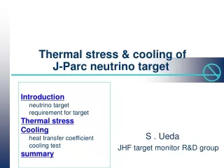
Target for JHF neutrino Requirements Solid target Easy to handle melting point should be high enough. Thermal shock resistance Candidate Graphite Target Melting point Thermal conductivity Thermal expansion Young’s modulus
Determination of the size (radius) of the target External conditions Temperature rise / pulse • Inner radius of the horn of the inner conductor (1st horn) minimum rtarget~10mm A.K.Ichikawa (heat load from radiation) DT (degree) f maximum rtarget~15mm (pions are not well focused) (Target needs to be embed in the 1st horn to focus pions efficiently.) inner conductor • Size of the beam • at the target Largerthan sr~0.4cm (for 24p mm mrad beam) Z (cm) Radius of the target : 10~15mm
Determination of the size (radius) of the target Yield of pions (=neutrinos) Smalleris better( reduce the absorption of pions) But even if we change diameter from20mm to 30mm, the difference of # of p is~5% Beam size ( sr = r/2.5 ) effect of the p absorption in this region is fairly small Typical angle of the p focused by the horn ~100mrad A.K.Ichikawa diameter (mm)
Energy deposit in the target Target and beam size dependence Carbon (density 1.81g/cm3) A.K.Ichikawa A.K.Ichikawa Maximum>460J/cm3 This time, we used the target withf=30mm in the calculations and the simulations.
Estimation the temperature rise Material properties used in the simulation Temperature dependences have to be taken into account. Specific heat increased at higher temp. Temperature rise is overestimated (Tokai Carbon G347) Maximum temperature rise (DTmax) Constant ~240K Temperature (K) Temp. dependent ~170K (W/mK ) (Tokai Carbon G347) Thermal conductivity decreased at higher temp. Temperature at the center of the target is underestimated (Still, far below the melting point) Temperature (K)
Estimation of the temperature rise Parameters = 6.5W/m2/K Thermal convection coefficient = 30oC (fixed) Temperature of the surrounding area just after the spill (after 5ms) just before the next spill (after 3.53s) M.Minakawa, Y.H.
Time dependence of temperature Maximum temperature Center (r=0mm) r=0mm,z=161mm far below the melting point Surface (r=15mm) r=15mm,z=700mm (temperature of the surrounding area was fixed at 30 oC) 4 8 12 32 (Sec.) M.Minakawa, Y.H. Consider direct water cooling To keep the surface temperature below 100oC, water temperature should not exceed ~50oC. Thermal convection coeff. needs to be larger than ~6kW/m2/K. Is it possible?
Cooling test According to the results from the calculations, heat transfer rate larger than ~6kW/m2/k. Heat up the target with DC current and try to cool by the flowing water. DC ~1.5kA ~20kW water DC Current measure water flow rate and temperature at various points estimate the heat transfer rate.
Cooling test set up heat transfer rate measurement water DC Current Water Thickness of the water path : 2mm Radius of the target: 15mm Water temp. (in) ~25oC DC Current: up to 1.3kA corresponds to ~ 20kW Current feeds Thermocouples
Cooling test results Results & calculations Theoretical formula This time we measured up to 12l/m. a = 0.023 x Re 0.8 x Pr 0.4 x l x d-1 Re Reynolds number Pr Prandtl number Generated heat l Thermal conductivity 5~20kW Calc. equivalent diameter d (Re and Pr also depend on the surface temp.) Data S.Ueda Measurements and theoretical calculations seem to agree a > 6kW/m2/k cab be achieved when the flow rate is more than 18l/m
Change of the material properties by neutron irradiation The thermal conductivity is largely reduced by the neutron irradiation effect ( about by factor 10.) T.Maruyama et al., J. of nucl. materials, 195(1992), 44-50 Reduce the thermal conductivity by factor 10 in the simulation. Temperature at the center was increased but it was saturated after 10 spills and themaximum temperature was less than 400 oC. (Temperature of the surface did not change or slightly reduced.) Effect of the neutron irradiation on thermal conductivity will not be the problem.
Actual design of the target Direct cooling or put in the container? This time, we tested the “direct cooling”. It seems to be working. But • The target will not be dissolved? • If water get into the deep inside of the target ... Boiled when the beam hits the target (?) • 90cm long target can not be made by using the best material. If we put the target in a metal container, water does not contact with the target, it is possible to cut the target in small pieces, even if the target brakes up, the target material does not flow away. We are planning to put the target in a container and measure the heat transfer rate.
Estimation of the thermal stress Material properties used in the simulation Thermal expansion coeff. Young’s modulus (GPa) (Tokai Carbon G347) (Tokai Carbon G347) Temperature (K) Temperature (K) If these temperature dependences are taken into account, the estimated thermal stress will be increased.
Estimation of the thermal stress (Analytical) Analytical calculations Young’s modulus E n Poisson ratio a linear expansion coeff. (thermal) T0 Temperature Manufacturer Type EquivalentTensile stress (MPa) strength (MPa) Toyo Tanso IG-43 ~7 37.2 ISO-88 ~11 68.6 Poco Graphite ZXF-5Q ~15 95.0 Tokai Carbon G347 ~6 31.4 Here, we do not have the data of temperature dependences of the material properties other than G347, we assume that the shape of the temperature dependences are the same.
Thermal stress estimation (ANSYS) Condition: Simulate the hottest part (z=100mm ~ 200mm) Both of the edges (z=100 & 200mm) are fixed (z direction). just after the spill (after 5ms) Equivalent stress maximum temperature @ maximum temperature (r=0,z~170mm) (r=0,z~170mm) 0 ~8.8MPa. (analytical calc: 6.0MPa) r (mm) [Tensile strength (Tokai Carbon G347) : 31.4MPa] 15 100 200 @ r=0, z=200mm z (mm) ~14.5MPa. (Because both of the edges were fixed) slightly larger but consistent with the analytical calculations (due to the approximation of the temperature distribution)
Water system for the target cooling We have to remove H2,N ions and heavy metal ions. Also, the water have to be cooled.(DT(water)~15oC@20l/min.) Service pit Underground machine pit Filters /Ion exchangers Target Area Degasser Target Heat ~20kW Water vol.= 1l Flow 20l/min. To the decay volume cooling system Buffer tank (0.1m3)
Radioactive residues (target and cooling water) 1) Target (By Nakano) size f=30mm, L=900mm density 1.8g/cm3 ~9x10¹²(Bq) # of generated Be7 ~14Sv/h after 1yr of running, cooled for 1day 2) Cooling water (By K.Suzuki) after 20 days of running Tritium ~30(MBq)
Summary (I) For the JPARC n experiment, solid target R&D is now ongoing. material Graphite ( or C/C composite ?) dimensions diameter ~30mm length 900mm (2 interaction length) cooling Water (direct or put in the case?) Heat transfer rate > ~ 6kW/m2/K cooling method Direct cooling seems to work Water flow rate ~20l/min. temperature rise ~ 175 oC (center) ~ 25oC (surface) thermal stress ~ 9MPa (for G347) [Tensile strength (G347) ~ 31MPa]
Summary (II) R&D Items (We want to test/check the following items.) • Cooling test Set the water flow rate at20l/min. and confirm the method. Measure the heat transfer rates with a target container. • Stress test Beam test(with same energy concentration) Where? • Irradiation effects other than the thermal conductivity • Search for the best material (Usually, graphite, whose tensile strength is large, has large Young’s modulus. the thermal stress is also getting larger.) Temperature dependences of the material properties.
40ton crane Ground level Service pit Concrete Beam window Iron shield Machine room He container Beam window Cooling Concrete Baffle Waste storage area Target+1st horn 2nd horn 3rd horn Summary (III) • Design of the entire system has to be fixed. How to fix (support) the target, alignments etc...
Remove horn/target move to the storage area concrete Waste storage area Iron shield Waste storage area Summary (IV) • Target handling How to remove the target from the horn remotely? (It may be necessary to remove the target from the horn when the target part is broken.)