Download
1 / 13
130 likes | 148 Views
This presentation discusses the design and cooling system of the J-PARC neutrino target, including the target station, horn system, and cooling pipes. It also explores the irradiation effects on the target and suggests further design studies.

E N D
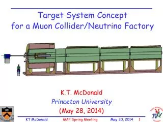
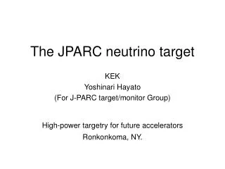
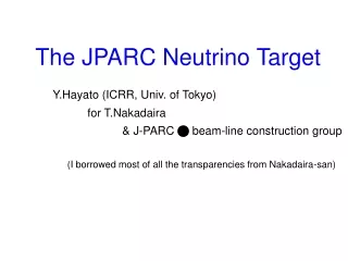
The JPARC Neutrino Target Y.Hayato (ICRR, Univ. of Tokyo) for T.Nakadaira & J-PARC n beam-line construction group (I borrowed most of all the transparencies from Nakadaira-san)
J-PARC neutrino beam line Primary Proton beam line Extraction point Target Target station Bunch structure Decay volume Spill width ~5ms 8 (15) bunches/spill beam dump muon monitor Cycle: 3~4 sec Near neutrino detector Bunch spacing: ~600(300) ns Bunch length: 58ns (Full width)
Accommodate Baffle: Graphite, 32mmf hole x 1.7m long to protect 1st horn Target 3 Horns Area filled with Helium gas reduce Tritium, NOx production Highly radio-activated ~1Sv/h, Need remote-controlled maintenance system Need cooling (Helium vessel, radiation shield,..) Target Station 3rd horn 2nd horn Trg& 1st horn Baffle Target Baffle beam 1st Horn 2nd Horn 3rd Horn
47.0 46.4 39.6 35.6 26.0 Target dimension • Co-axial 2 layer cooling pipe: Graphite / Ti-6Al-4V,Helium cooling Outer pipe Ti-6Al-4V [mm] Inner pipe IG-43 target IG-43 spacer Sectional area = 4.610-4 [m2] Cooing path f=47mm f=26mm
One design of the target & surrounding cooling pipe (Not the final design). 陽子ビーム He inlet He outlet Ti-6Al-4V Beam window Ti-6Al-4V 陽子ビーム Target Need further design study Graphite IG-43
} To downstream } To downstream Design of inlet and outlet of He Gas is not fixed.
Target cooling : Water or Helium? Advantage Disadvantage
Target : Conceptual design • Core: Isotropic-Graphite : IG-43 (Toyo Tanso Co. Ltd) • Energy deposit… Total: ~40kJ/spill (30GeV) DT 200K. seq = 7.5 [MPa] Tensile strength = 37.2 [MPa] Distribution of the energy deposit in the target (w/ 1 spill) J/gK degree MARS proton beam cm f=47mm f=26mm
Expected radiation damage of the target The approximation formula used by NuMI target group : 0.25dpa/year MARS simulation : 0.15~0.20 dpa/year Dimension change : shrinkage by ~5mm in length in 5 years at maximum.~75mm in radius Degradation of thermal conductivity … decreased by 97% @ 200 C70~80% @ 400 C Magnitude of the damage strongly depends on the irradiation temperature. It is better to keep the temperature of target around400 ~ 800 C 800oC 400oC Thermal conductivity (After/Before) (dpa) 1 2 3 Irradiation Effect of Graphite 800 1000 400 600 Irradiation Temperature(C) JAERI report (1991) 2dpa -0.5% 1dpa Dimension change Toyo-Tanso Co Ltd. IG-11
Max: ~ 500 C Min: ~ 300 C Max: ~160 C (DT = 135 C) Avg. : ~380 C Avg. : ~40 C FEM simulation of He cooling • Assumptions: 0.19MPaHe Initial temperature: 25 CHe flow rate: 6000 [l/min] 194 [m/sec]Heat convection rate: 820 [W/m2/K] (50GeV,f=15mm) Target Temperature Helium Temperature
38C ~34C ~102C 25C 160C 395C ~380C ~300C 500C FEM simulation of He cooling (50GeV,f=15mm) • Assumptions: 0.19MPa(Possible pressure drop at the downstream of target is taken into account.) • He Initial temperature: 25 CHe flow rate:6000 [l/min] 194 [m/sec]Heat convection rate:820 [W/m2/K]