Download
1 / 13
130 likes | 290 Views
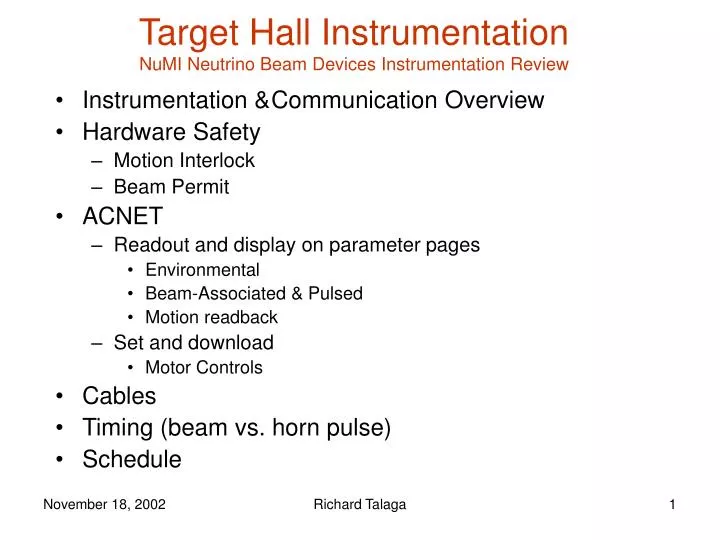
Target Hall Instrumentation NuMI Neutrino Beam Devices Instrumentation Review. Instrumentation & Communication Overview Hardware Safety Motion Interlock Beam Permit ACNET Readout and display on parameter pages Environmental Beam-Associated & Pulsed Motion readback Set and download

E N D
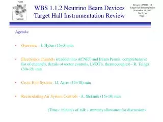
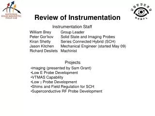
Target Hall InstrumentationNuMI Neutrino Beam Devices Instrumentation Review • Instrumentation & Communication Overview • Hardware Safety • Motion Interlock • Beam Permit • ACNET • Readout and display on parameter pages • Environmental • Beam-Associated & Pulsed • Motion readback • Set and download • Motor Controls • Cables • Timing (beam vs. horn pulse) • Schedule Richard Talaga
Instrumentation & Communication Overview • Instruments • Environmental, such as • Temperature • Pressure • Humidity • Synchronous with the beam, such as • Horn magnetic field: “Bdot” • Beam on target: Budal Monitor • Beam/Horn alignment: Beam Loss Monitor (BLM) • Timing: Horn current relative to Beam • Motion Control & Readback • Horn 1 angle & transverse • Baffle/Target angle & transverse • Baffle/Target longitudinal Richard Talaga
Instrumentation & Communication Overview • Communication with ACNET • ACNET Input Sources • Analog Entry Box (AEB) MADC CAMAC • Environmental sensors (temperatures, pressures…) • Beam Permit(AEB Process Channel Interface Permit) (15 Hz sampling) • Beam-Synchronous signals (Bdot, BLM, …) • PLC ethernet front-end processor ACNET • A less expensive option to condition thermocouple signals (described in Andy Stefanik’s talk) • Motor Control: ACNET InputethernetACSmotor • Motion Control Position readback ACNET • Alarms • Limits entered into database Richard Talaga
Instrumentation Data to ACNET AEB Sensor Conditioner MADC CAMAC Beam Permit PCI PLC Ethernet Sensor Richard Talaga
Hardware Safety • Motion Interlock • Prevent Target from colliding with Horn 1 • Target range: 20cm vertical, 250 cm longitudinal • Disable transverse motion of target and horn 1 when: • Target is not at beam height • Target is moved into horn 1 beyond a critical point • 2.7 mm clearance at max insertion if centered • Beam Permit • Beam permit dropped if values are outside limits • Baffle Temperatures • Air Supply Temperature • Air Supply Fan Differential Pressure Richard Talaga
ACNET Data23 AEB channels, 42 PLC channels, 9 Motors Richard Talaga
Motor Control Richard Talaga
Motor Control • VME Crate* • MVME Processor* with ethernet connection to ACNET • VME Carrier Board with 5 IP Stepper Motor Modules • Each Stepper Module handles 2 Motors & 4 Limit Switches • Stepper module communicates with ACS motor modules • VME Carrier Board with 1 IP A/D Module • LVDT readback • ACS Crates • Two crates & one power supply • 9 ACS motor modules • Cables & connectors *supplied by controls dept. Richard Talaga
Motor Controls Limit Switches IP Carrier Boards ACS Crate Ethernet Module VME Motor Motor Module Processor ADC Conditioner LVDT Richard Talaga
Instrumentation List Richard Talaga
Cables • In high radiation area (beam line & beam devices) • Radiation-hard cable routed up to patch panels ontop of modules • Budal (Tgt current), Baffle, Bdot, Baffle & Horn Temperatures • Rad-hard cable: MgO insulation, two conductors in a metal sheath • Custom-fabricated connector mounts • Connect beamline cables with module “penetration” cables • BLM HV cable: must withstand several kV • “Home-made” coaxial cable with ceramic insulators • Straight shot…no bends • Patch panels PS Room • Patch panels for rad-hard beamline cables conventional cables • Motors, LVDTs, sense switches, some thermocouples… conventional cables • All signals to Power Supply Room via RAW Room Richard Talaga
Timing • Ensure that horn pulse peaks in time with beamspill • Goal: within 10 µs (150 µs mismatch 1% lower field) • Budal or BLM signal for beam timing • BLM will probably be saturated • Bdot or PS transducer for horn pulse timing • Horn pulse is ~2 ms long half-sine wave • Timing Hardware: to be designed • Custom made TDC with ~200 usec range; 0-10V AEB • Alarm issued if timing outside limits Richard Talaga
Schedule • Prototype or “Representative System” in MI8 • Definition of Instrumentation December ’02 • Real Signals, for example • Thermocouples, Bdot, Stripline Current • Fake Signals, for example • Budal, BLM • Motors, Limit Switches & LVDTs • AEB & PLC channels in ACNET • First test of Motor Controls in MI8 March ‘03 • Trial run of “representative system” in MI8 Mar-Aug ‘03 • Installation in PS Room January’04 • Signal Conditioners, etc. • Installation in Target HallMay-July ’04 • Sensors, cabling, patch panels, etc. Richard Talaga