16.317: Microprocessor System Design I
16.317: Microprocessor System Design I. Instructor: Dr. Michael Geiger Spring 2012 Lecture 5: Stack, I/O address space, assembly programming intro. Lecture outline. Announcements/reminders Register for the discussion group on piazza.com Search by course # “16.317”, semester Spring 2012

16.317: Microprocessor System Design I
E N D
Presentation Transcript
16.317: Microprocessor System Design I Instructor: Dr. Michael Geiger Spring 2012 Lecture 5: Stack, I/O address space, assembly programming intro
Lecture outline • Announcements/reminders • Register for the discussion group on piazza.com • Search by course # “16.317”, semester Spring 2012 • Course handouts on: http://mgeiger.eng.uml.edu/16317/sp12 • HW1 posted; due 2/10 • Lab 1 to be posted shortly • Lecture outline • Review • Real mode address generation • Today • Stack • I/O address space • Assembly programming overview Microprocessors I: Lecture 5
Review • Logical vs. physical addresses (in 386) • Logical address: base/offset register pair • i.e. CS:IP, DS:SI, SS:SP • Physical address: actual address in memory • In 386, calculate by shifting base left by 4 bits, adding offset • Example: CS = 0x1000 and IP = 0x1234 Physical addr. = 0x10000+ 0x1234 = 0x11234 • Can have multiple logical addresses mapping to same physical address: aliases Microprocessors I: Lecture 5
The Stack • Stack—temporary storage area in stack segment of memory • Real mode—64K bytes long • Organized as 32K words • Information saved as words or double words, not bytes • Organization of stack • SS:0002H end of stack (lowest addressed word) • SS:FFFEH bottom of stack (highest addressed word) • SS:SP top of stack (last stack location where data was pushed) • Stack grows down from higher to lower address • Used by call, push, pop, and return operations PUSH ESI causes the current content of the ESI register to be pushed onto the stack POP ESI causes the value at the top of the stack to be popped back into the ESI register Microprocessors I: Lecture 5
The Stack - Push Stack Operation • Status of the stack prior to execution of the instruction PUSH AX AX = 1234H SS = 0105H AEOS = SS:02 01052H = end of stack SP = 0008H ATOS = SS:SP 01058H = current top of stack ABOS = SS:FFFE 1104EH BBAAH = Last value pushed to stack Addresses < 01058H = invalid stack data Addresses >= 01058H = valid stack data • In response to the execution of PUSH AX instruction 1. SP 0006 decremented by 2 ATOP 01056H 2. Memory write to stack segment AL = 34H 01056H AH = 12H 01057H Microprocessors I: Lecture 5
The Stack- Pop Stack Operation • Status of the stack prior to execution of the instruction POP AX AX = XXXXH SS = 0105H SP = 0006H ATOS = SS:SP 01056H = current top of stack 1234H = Last value pushed to stack Addresses < 01056H = invalid stack data Addresses >= 01056H = valid stack data 1 2 execution of POP AX instruction 1. Memory read to AX 01056H = 34H AL 01057H = 12H AH 2. SP 0008H incremented by 2 ATOP 01058H execution of POP BX instruction 1. Memory read to BX 01058H = AAH BL 01059H = BBH BH 2. SP 000AH incremented by 2 ATOP 0105AH Microprocessors I: Lecture 5
Stack examples • Given the following register values: • SS = 0x3170 • SP = 0xFFFE • Stack is initially empty • EAX = 0x12345678 • EBX = 0xDEADBEEF • ECX = 0x0000FFFF • EDX = 0x11223344 • What is the state of the stack and the registers after the following sequence? • PUSH AX • PUSH BX • PUSH CX • POP DX • PUSH AX • POP BX • POP AX • PUSH DX Microprocessors I: Lecture 5
I/O Address Space • Input/output address space • Place where I/O devices are normally implemented • I/O addresses are only 16-bits in length • Independent 64K-byte address space • Address range 0000H through FFFFH • Page 0 • First 256 byte addresses 0000H - 00FFH • Can be accessed with direct or variable I/O instructions • Ports F8H through FF reserved Microprocessors I: Lecture 5
Organization of the I/O Data • Input/output data organization • Supports byte, word, and double-word I/O ports • 64K independent byte-wide I/O ports • 32K independent word-wide I/O ports • 16K independent double-word-wide I/O ports • Examples (aligned I/O ports): Byte ports 0,1,2 addresses 0000H, 0001H, and 0002H Word ports 0,1,2 addresses 0000H, 0002H, 0004H Double-word ports 0,1,2 addresses 0000H, 0004H, 0008H • Advantages of Isolated I/O • Complete memory address space available for use by memory • I/O instructions tailored to maximize performance • Disadvantage of Isolated I/O • All inputs/outputs must take place between I/O port and accumulator register Microprocessors I: Lecture 5
Software • Instruction -> Program -> Software • Machine language -> Assembly Language -> High Level Language (C/C++, Java) • Source code -> Object code -> Executable • Assembly language • Instruction: Label: Instruction ; comment Example: START: MOV EAX, EBX; COPY EBX INTO EAX • List file: line number, offset, machine language (code), instruction, comments Microprocessors I: Lecture 5
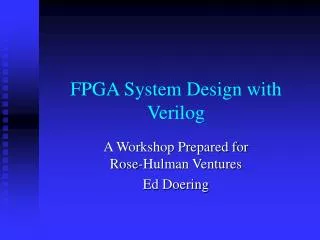
Assembly Language Program Development Assemble the program Describe the problem Yes Syntax error Plan steps of solution Object module No flowchat LINK the program Implement flowchat using Assembly language Execute and debug Handwritten source program Yes logic error done No Enter/edit source program Assembler source program Microprocessors I: Lecture 5
Instruction set Defines the basic operations a programmer can make the microprocessor perform 8088/8086 instruction set contains 117 basic instructions The 80386DX Base Instruction Set Microprocessors I: Lecture 5
Instruction Set Compatibility • The 80x86 instruction set has evolved in an upward compatible manner • Base instruction set 8088/8086 processor • Extended instruction set 80286 processor • System control instruction set 80286 processor • 80386 specific instruction set 80386DX/SX • 80486 specific instruction set 80486DX/SX • Pentium specific instruction set Original Pentium processor Microprocessors I: Lecture 5
Instruction groups Instructions are organized into groups of functionally related instructions Data Transfer instructions Input/output instructions Arithmetic instructions Logic instructions String Instructions Control transfer instructions Processor control Instruction Groups Microprocessors I: Lecture 5
Instruction Assembly Notation • Each instruction is represented by a mnemonic that describes its operation—called its operation code (opcode) • MOV = move data transfer • ADD = add arithmetic • AND = logical AND logic • JMP = unconditional jump control transfer • Operands are the other parts of an assembly language Instructions • Identify whether the elements of data to be processed are in registers or memory • Source operand– location of one operand to be process • Destination operand—location of the other operand to be processed and the location of the result Microprocessors I: Lecture 5
Native language of the 8088/8086 (PC) is machine language (code) One to one correspondence to assembly language statements Instructions encoded with 0’s and 1’s Machine instructions can take up from 1 to 6 bytes Example: Move=MOV The wide choice of register operands, memory operands, and addressing mode available to access operands in memory expands the move instruction to 28 different forms Ranges in size from 2 to 6 bytes Machine Language Microprocessors I: Lecture 5
General structure of an assembly language statement LABEL: INSTRUCTION ;COMMENT Label—address identifier for the statement Instruction—the operation to be performed Comment—documents the purpose of the statement Example: START: MOV AX, BX ; Copy BX into AX Other examples: INC SI ;Update pointer ADD AX, BX Few instructions have a label—usually marks a jump to point Not all instructions need a comment Structure of an Assembly Language Statement Microprocessors I: Lecture 5
Next time • Basic assembly program structure • Addressing modes (intro) Microprocessors I: Lecture 5