Download
1 / 32
320 likes | 429 Views
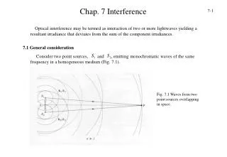
Chap. 7 Interference. Optical interference may be termed as interaction of two or more lightwaves yielding a resultant irradiance that deviates from the sum of the component irradiances. 7.1 General consideration.

E N D
Chap. 7 Interference 7- Optical interference may be termed as interaction of two or more lightwaves yielding a resultant irradiance that deviates from the sum of the component irradiances. 7.1 General consideration Consider two point sources, and , emitting monochromatic waves of the same frequency in a homogeneous medium (Fig. 7.1). Fig. 7.1 Waves from two point sources overlapping in space.
7- Locate the point of observation far enough away from the sources so that at the wavefronts will be planes, as shown in Fig. 7.2. For the moment, we will consider only linearly polarized waves (7.1a) and Fig. 7.2 Two plane waves meet at P. (7.1b) The resultant wave at can be given by The irradiance is defined as
7- Inasmuch as we will be concerned with relative irradiance within the same medium, we will simply neglect that constants and set Obviously, Taking the time average of both sides, we find that the irradiance becomes provided that
7- and The latter expression is known as the interference term. To evaluate it in this specific instance, we form The interference term is then and , equal to is the phase difference arising from a combined path-length and initial phase-angle difference. Notice that if and are perpendicular, and The most common situation in the work to follow corresponds to parallel to . In that case, the irradiance reduces to the value found in the scalar treatment. Under those conditions
7- This can be written in a more convenient way by noticing that and The interference term becomes So, the total irradiance is At various points in space, the resultant irradiance can be greater, less than, or equal to , depending on the value of , that is, depending on . A maximum in the irradiance is obtained when so that
7- when In this case the phase difference between the two waves is an integer multiple of , and the disturbances are said to be in phase. One speaks of this total constructive interference. When the waves are out of phase, , and the result is known as constructive interference. At , the disturbances are said to be out of phase, and For we have the condition of destructive interference, When a minimum in the irradiance is obtained It is referred to as total destructive interference. Another somewhat special yet very important case arises when the amplitudes of both waves reaching in Fig. 7.1 are equal. Let . Eq. 7.12 can now be written as
7- from which it follows that and Equation 7.12 holds equally well for the spherical waves emitted by and . Such waves can be expressed as and The terms and are the radii of the spherical wavefronts overlapping at . In this case Equation 7.15 becomes
7- The maximum irradiance occurs when and minimum when where and If the waves are in phase at the emitter, and Eqs. 7.19a and 7.19b can be simplified to for maximum and minimum irradiance, respectively.
7- 7.2 Young’s double-slit interference experiment In 1801, Thomas Young experimentally proved that light is a wave. He did so by demonstrating that light undergoes interference, as do water waves, sound waves, and waves of all other types. We shall here examine Young’s historic experiment as an example of the interference of light waves. Fig. 7.3 gives the basic arrangement as an example of the interference of light waves. Fig. 7.3 Young’s interference experiment.
7- Light form a distant monochromatic source illuminating slit in screen . The emerging light spreads via diffraction to illuminate two slits and in screen The light waves traveling from the two slits overlap and undergo interference, forming an interference pattern of maxima and minima on viewing screen as shown in Fig. 7.4. Fig. 7.4 A photograph of an interference pattern produced by the arrangement shown in Fig. 7.3. The interference pattern consists of alternating bright and dark bands which are called bright fringes and dark fringes, respectively. What exactly determines the locations of the fringes? To answer, we shall use the arrangement in Fig. 7.5(a). There, a plane wave of monochromatic light is incident on two slits and in
7- screen B; the light diffracts through the slits and produces an interference pattern on screen C. We draw a central axis from the point halfway between the slits to screen C as a reference. We then pick, for discussion, an arbitrary point P on the screen, at angle to the central axis. This point intercepts the wave of ray from the bottom slit and the wave of from the top slit. Notice that these waves are in phase when they pass through the two slits because there they are just portions of the same incident wave. But once they have Fig. 7.5 (a) Waves from and combine at . (b) For we can approximate rays and as being parallel.
7- passed the slits, the two waves must travel different distances to reach . The path length distance can be given provided the distance from the slits to the screen is much grater than the slit separation . For bright fringes, we must have For dark fringes, the requirement is With Eq. 7.22 and 7.23, we can find the angle to any fringe and thus locate that fringe. Further we can use the values of and to label the fringes. For , Eq. 7.22 tells us that a bright fringe is at , that is on the central axis. Now let us consider the irradiance. According to Eq. 7.18, the resultant irradiance
7- is given by where Fig. 7.6 shows the irradiance of a double-slit interference pattern as a function of the phase difference between the waves from the two slits. Fig. 7.6 Idealized irradiance versus the phase difference.
7- 7.3 Double beam interference: interference from thin films Interference effects are observable in sheet transparent materials for a given wavelength of electromagnetic radiation when their thickness is of the order of that wavelength. Consider a thin transparent film with a thickness illuminated by a monochromatic light of wavelength (Fig. 7.7). The optical path-length difference for the first two reflected beams is given by and since Fig. 7.7 Ray representation of thin-film interference.
7- Now, to find an expression for write if we make use of Snell’s law, this becomes where The expression for now becomes
7- or finally The corresponding phase difference associated with the optical path-length difference is then just the product of the free-space propagation number and that is, Notice that in either case there will be an additional phase shift arising from the reflection themselves. For incident angles up to , regardless of the polarization of the incoming light, the two beams, one internally and one externally reflected, will experience a relative phase shift of radians. Accordingly, and more explicitly When in other words, an even multiple of , an interference maximum, a bright spot, appears at . In that case Eq. 7.26 can be rearranged to
7- where use has been made of the fact that . Interference minima in reflected light result when that is, odd multiples of . For such cases Eq. 7.26 yields The appearance of odd and even multiples of in Eqs. 7.27 and 7.28 is rather significant, as we will see presently. For an extended source, light will reach the lens from various direction, and the fringe pattern will spread out over a large area of the film (Fig 7.8). The angle or equivalently , determined by the position P, will in turn control . The fringes appearing at position P1 and P2 in Fig 7.8 are, accordingly, known as fringes of equal inclination. Each source point on the extended source is incoherent with respect to the others. Fig 7.8 All rays inclined at the same angle arrive at the same point
7- 7.4 Multiple-beam interference Fig 7.9 Figure 7.9 shows a multiple beam interference on a transparent film. As before, r and t denote reflection and transmission amplitude coefficients when the incident beam is out of the film while r’ and t’ when the incident beam is inside the film. Since all beams are almost parallel to each other so their electric field directions are also almost parallel to each other. As a consequence, we can use scalar to describe the electric field. The amplitudes of the reflected beams are:
7- E0 is the incident electric field. is the phase arising from an optical path-length difference between adjacent rays. d and are the film thickness and the refraction angle inside the film respectively. The relative phase shift undergone by the first ray as a result of the reflection is embodied in the quantity r’. The resultant reflected scalar wave is then When and the number of terms in the series approaches infinity, we have
7- In the case of zero absorption, the Stock’s relations hold: r’=-r and tt’=1-r2. We have The reflected irradiance at point P is
7- Similarly the amplitudes of the transmitted waves given by Multiplying this by its complex conjugate, we obtain the irradiance of the transmitted beam
7- For the non-adsorbing film, Eqs (7. 32) and (7.35) show that Ir / Ii + It / Ii = 1 (7.36) Figure 7.10 shows It/Ii as a function of the phase . Fig 7.10 Transmitted irradiance The later condition is the same as Eqn. (7.26) for two-beam interference. When a thin film surface is coated with adsorbing material (metal) to increase the reflection coefficient, Eqn (7.36) doesn’t hold. The transmitted intensity is modified to So the maximum and minimum conditions above still hold.
7- Fig 7.12 Transmitted light pattern from a Fabry-Perot interferometer Fig 7.11 Fabry-Perot interferometer A Fabry-Perot interferometer is shown in figure 7.11. Two semi-silvered glass optical flats form the reflecting boundary surfaces. The enclosed air gap ranges from millimeters to centimeters. The un-silvered sides of the plates are made to have a slight wedge shape (a few minutes of arc) to reduce the interference pattern arising from reflections off these sides. The interferometer is illuminated by a broad source, which might be a He-Ne laser beam spread out in diameter to several centimeters. Only one ray emitted from some point S1 on the source is traced. Entering by way of the plate, it is multiply reflected within the gap. The transmitted rays are collected by a lens and brought to a focus on a screen. Consider this particular plane of incidence, which contains all the reflected rays. Any other ray emitted from a different point S2, parallel to the original ray will form a spot at the same point P on the screen. Eq. (7.37) determines the transmitted irradiance. The multiple waves generated in the cavity, arriving at P from either S1 or S2, are coherent among themselves.
7- But the rays arising from S1 are completely incoherent with respect to those from S2. The contribution to the irradiance It at P is just the sum of the two irradiance contribution. All the rays incident on the gap at a given angle will result in a single circular fringe of uniform irradiance (Fig 7.12). With a broad diffuse source, the interference bands will be narrow concentric rings. A Fabry-Perot interferometer can be used to measure the wavelength difference of two closed spectral lines.
7.5 Anti_reflection and reflection-enhance coatings 7- A substrate-air system can be modified to substrate-films-air system to either reduce or enhance the light reflection back to air. Consider the linearly polarized wave shown in Fig. 7.13, impinging on a thin dielectric film between two semi-infinite transparent media. Each wave and so forth represents the resultant of all possible waves traveling in that direction, at that point in the medium. The summation process is therefore built in. The boundary conditions require that the tangential components of both the electric ( ) and magnetic ( ) Fields be continuous across the boundaries. At boundary I 7.13 Fields at the boundaries
7- Where use is made of the fact that and are related through the index of refraction and the unit propagation vector . At boundary II In accord with Eq. (7.25), a wave that traverses the film once undergoes a phase shift of So, The solution of (7.44) is
7- are the refractive index, the thickness and the beam incident angle in the jth film, respectively. With the help of equations (7.38) and (7.41), equation (7.48) is expanded to For electric field parallel to the incident plane, equations (7.48) through (7.53) are still valid except for the Y expression in (7.50). It should be replaced by
Let’s calculate the reflectance when one layer of film presents. With Y0, Y1 and Ys defined in equation (7.50) and the matrix M=M1 defined in equation (7.49), equation (7.52) becomes 7- So (7.58) becomes the same as (7.32) noting that
7- Now consider the extremely important case of normal incidence, where all From the single layer formula (7.57), we have (p=1) To make the film important to the reflectance, one choose Generally, the thickness d1 is chosen to satisfy (7.63) for yellow-green portion of the visible spectrum, where the eye is most sensitive. MgF2 (n1=1.38) on a glass substrate (ns=1.5), can reduce the reflection coefficient from 4% to 1% in the visible region.
7- For a double layer, quarter-wavelength antireflection coating as shown on the left panel in Fig 7.14, M=M1M2, or more specifically Put (7.65) into Eq. (7.52), we have Fig 7.14 A periodic structure It’s easier to satisfy (7.77) than that (7.63). Since ns>n0, from (7.77) n2>n1. Accordingly, it is common to design a (glass)-(high index)-(low index)-(air) system as gHLa, as shown in Fig. 7.14. Zirconium dioxide (n=2.1), titanium oxide (n=2.40) and zinc sulfide (n=2.32) are commonly used for H-layers. Magnesium fluoride (n=1.38) often serves as L-layers
7- Eq. (7.67) can be used in the opposite way. If one choose n2/n1>>1, one will have a reflection-enhanced system. To further enhance the reflection, one can use a periodic quarter-wave stack system g(HL)ma as shown in the right panel of figure (7.14) where m=3. The corresponding matrix for the system is Fig 7.15 Reflectance and transmittance for several periodic systems When nH/nL>>1 and m is large the reflectance can be very high. More improvement can be achieved by adding one more high-index layer to the air side of the periodic system to become g(HL)mHa system. The reflectance and transmittance are shown in figure 7.15 for several periodic systems.