Download

1 / 60
630 likes | 966 Views
Optical Fibre Communication. Lecture delivered by Christie Alwis 2009 faculty of Applied Science for computer science , and physics special students. University of Sabaragamuwa , Belihuloya. For more details on this lecture, please visit www.christiealwis.com. Revolutions.

E N D
Optical Fibre Communication • Lecture delivered by Christie Alwis • 2009 faculty of Applied Science for computer science , and physics special students. • University of Sabaragamuwa , Belihuloya. • For more details on this lecture, please visit www.christiealwis.com
Revolutions • How it's going to be affected to the human being? • Industrial Revolution • Agricultural Revolution • Communication Revolution a.) can talk with the use of latest Technology @ any where in the world, @ low cost. b.) can be accepted knowledge @ anywhere in the world. (e- Assessment)
WHAT IS COMMUNICATION NETWORK Local Area Node Country A Domestic Transport Network (OF, IG Undersea Optical Fiber Networks International Transport Network IG Country B Both Domestic and International Transport will be on Optical Fibers. And Switching Nodes will be on NGN.
BASIC COMPONENTS OF COMMUNICATION NETWORKS • Following 8 major components can be identified • Geographical Location & Terminal • Access Networks • Local Exchange • Domestic Transport Network • International Exchange • International Transport Network • Other Country International Exchange • Other Country Domestic Network (With the similar components as above)
DEVELOPMENT OF ACCESS NETWORK TV Power Telephone ? • Radio Options: 3G, EvDO, WiMAX • xDSL, PON, and PLC Access Network is developed to accommodate integrated services such as Internet, IPTV, Data with Voice
Theoretical capacities of other Medias • Cu=Short distance could for a 8Mbps Similarly : • Microwave radio=STM 16 =More than 2.5Gbps • Satellite=STM 1= 155.52 Mbps • Coaxial cable=Approximately 1.5 Gbps
Basic principle of dispersion • Dispersion is a little complex than attenuation • Dispersion is a process whereby optical pulses are widened as they travel along an optical fibre. It is caused by the different wavelength components of a light signal of finite spectral width traveling down the fiber at different velocities.The effect is a pulse at the terminating end of a fibre that is a wider than the original pulse that was transmitted.If the amount if widening is excessive, the individual pulses will not be distinguishable by the receiver. OUT IN
Chromatic Dispersion • Variation of refractive index with wavelength of light • The two main underlying mechanisms, material dispersion and waveguide dispersion, naturally cancel one another, giving a zero dispersion point 0 • Control of the refractive index profile can place 0 anywhere in the 1300/1550nm wavelength range • The fibre characteristics are controlled by careful design of the chemical composition (doping) of the glass used • Dispersion is quoted in terms of the dispersion parameter ‘D’ with units ps/(nm.km) • An indication of the pulse broadening is given by: (D * (spectral width of the optical source) *(link distance))
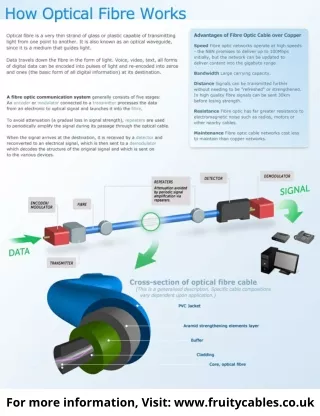
Optical transmission system concepts The basic components – A serial bit stream in electrical form is presented to a modulator, which encodes the data appropriately for fibre transmission
Basic Concept of LED • Like a normal diode, the LED consists of a chip of semiconducting material impregnated, or doped, with impurities to create a p-n junction. As in other diodes, current flows easily from the p-side, or anode, to the n-side, or cathode, but not in the reverse direction. Charge-carriers—electrons and holes—flow into the junction from electrodes with different voltages. When an electron meets a hole, it falls into a lower energy level, and releases energy in the form of a photon.
Contd…. • The wavelength of the light emitted, and therefore its color, depends on the band gap energy of the materials forming the p-n junction. In silicon or germanium diodes, the electrons and holes recombine by a non-radiative transition which produces no optical emission, because these are indirect band gap materials. The materials used for the LED have a direct band gap with energies corresponding to near-infrared, visible or near-ultraviolet light.
Power ratio (Decibel;dB) • The decibel (dB) is a logarithmic unit of measurement that expresses the magnitude of a physical quantity (usually power or intensity) relative to a specified or implied reference level. Since it expresses a ratio of two quantities with the same unit, it is a dimensionless unit.
Examples • To calculate the ratio of 1 kW (one kilowatt, or 1000 watts) to 1 W in decibels, use the formula • Similarly for amplitude ,current or voltage, (power is proportional to the square of the above 3 quantities. )
Answer (Example 1) • Connector loss= 8*1dB= 8dB • Cable loss= (4*100)/1000=0.4dB • System margin = 5dB • Sensitivity= -30 dB • Transmitter Power = connector loss+cable loss+system margin+sensitivity • = 8+0.4+5-30= -16.6dB Transmitter Receiver 8 Connectors
Answer (Example 2) Transmitter Receiver 2 Connectors • Connector loss= 2*1.5dB = 3 dB • Cable loss= 0.4dB * 50 = 20 dB • System margin = 8 dB • Sensitivity= -34 dB • Transmitter Power = connector loss+cable loss+system margin+sensitivity • = 3+20+8-34= -3 dB • No: of splices= 3/ 0.15 = 20 splices
C=fλ C= 3* 108 m/s
Future of optical fibre The following 2 major factors plays a vital role in designing the maximum capacity of an optical fibre • How far the digital multiplexing can be achieved • As at present , 488ns micro information of a bit pertaining to 2Mbps pcm stream will be shrinked to 25ps when it goes through stm 64 (10Gbps).If the technology improves to shrink less than 25ps , then the no of bits in the higher order pcm will be more than 10Gbps. • To transmit 10Gbps , the bandwidth required in the optical fibre is around 0.078ns = 78ps ( for 1 wavelength) • If the available bandwidth in the optical fibre is 200ns , the no; of wavelengths that can be produced is around 2400 , which will result in producing a total of 24Tbps. • Hence both time division multiplexing and dense wave division multiplexing can further improve the traffic carrying capacity of an optical fibre up to a total of 24Tbps.
Future scenarios Theoretical Maximum of an optical fibre cable No of wavelengths = ( 24 * 103 Gb ) / 10 Gb = 2400 wavelengths Transponders λ1 488 ns 25 ps 1 TDM Optical Fibre 2 λ2 2 Mbps 10Gbps λ2399 2399 Only 1 core is needed 2400 λ2400