Download
1 / 20
200 likes | 291 Views
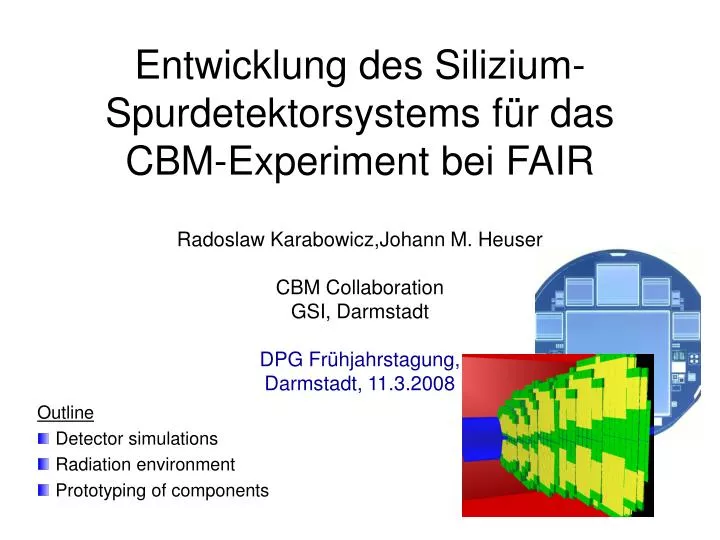
Entwicklung des Silizium-Spurdetektorsystems f ür das CBM -Experiment bei FAIR. Radoslaw Karabowicz,Johann M. Heuser CBM Collaboration GSI, Darmstadt DPG Fr ü hjahrstagung, Darmstadt, 11.3.2008. Outline Detector simulations Radiation environment Prototyping of components. CBM @ FAIR.

E N D
Entwicklung des Silizium-Spurdetektorsystems für das CBM-Experiment bei FAIR Radoslaw Karabowicz,Johann M. Heuser CBM Collaboration GSI, Darmstadt DPG Frühjahrstagung, Darmstadt, 11.3.2008 • Outline • Detector simulations • Radiation environment • Prototyping of components
CBM @ FAIR the Compressed Baryonic Matter Experiment Facility for Antiproton and Ion Research GSI as of 2008 SIS 100/300 DPG Conference, Mar 11th 2008 Radoslaw Karabowicz 2
CBM Experimental Setup MUon CHamber Time Of Flight Electro CALorimeter Ring Imaging CHerenkov Transition Radiation Detector • Silicon Tracking System: • 8 double-sided micro-strip • silicon stations • length of 100cm • with thickness of 300mm • and acceptance of about • 2.5 to 25 degrees • 1.3 million channels • -readout electronics, • support structures, • cables implemented Dipole Magnet Micro- Vertex Detector + Silicon Tracking System DPG Conference, Mar 11th 2008 Radoslaw Karabowicz 3
Tracking challenge Au+Au central collision at 25 AGeV (UrQMD): → ~1000 charged particles → ~700 in the STS detector acceptance Goal is to track particles: -quickly -efficiently -effectively 107 minimum bias collisions per second have to by analyzed online Hit densities in central part exceed 10/cm2/central event To perform physics analysis high tracking efficiency with good momentum and position resolution is crucial Tracking challenge DPG Conference, Mar 11th 2008 Radoslaw Karabowicz 4
High granularity detector Sensors’ occupancy in one Au+Au central 25 AGeV collision Double-sided micro-strip sensor horizontal size 6cm 60 mm station 1 ( at 30 cm) station 8 (at 100cm) vertical size from 2 to 6cm 15º rotated back side strips vertical front side strips DPG Conference, Mar 11th 2008 Radoslaw Karabowicz 5
Low mass detector y[cm] x[cm] station 5 (z = 60cm) x/x0 Radiation length thickness 6 million 10 GeV/c pions in Geant STS detector x/x0 • - silicon detector thickness: • currently 0.3% x0 (300mm) • station with cables and support • structure: up to 1% x0 • total vertex/tracking system: < 15% x0 DPG Conference, Mar 11th 2008 Radoslaw Karabowicz 6
Tracking results - 1000 central Au+Au collisions simulated in UrQMD, - transported in the STS geometry by GEANT, - track finding: Cellular Automaton, - track fitting: Kalman Filter. Track finding and fitting takes 78ms on Pentium4 processor DPG Conference, Mar 11th 2008 Radoslaw Karabowicz 7
Radiation environment Mrad Ionizing dose Ansatz: CBM Lifetime: 3x10¹⁴ minimum bias collisions Maximum dose at a level of around 20 Mrads station 5 (z = 60cm) station 1 (z = 30cm) Mrad station 8 (z = 100cm) Mrad DPG Conference, Mar 11th 2008 Radoslaw Karabowicz 8
Radiation environment cont’d STS 5 STS 6 STS 1 • neutron fluence • 1 MeV n equivalence • minimum bias • Au+Au collision at • 25 AGeV (UrQMD) • transported in • FLUKA • CBM lifetime: • ~3 x 10¹⁴ interactions 1015 1014 1013 1012 1011 1015 1014 1013 1012 1011 STS 7 STS 8 1015 1014 1013 1012 1011 1015 1014 1013 1012 1011 More than3 x 1014 neutron equivalents per square centimeter !! LHC radiation regime !! DPG Conference, Mar 11th 2008 Radoslaw Karabowicz 9
Hardware development Long, stiff, low material support structures ALICE design Modular structure Station 1 readout cables sensors support Expertise in Russia DPG Conference, Mar 11th 2008 Radoslaw Karabowicz 10
Readout and cables Fast, self-triggering, precise, radiation tolerant readout chip n-XYTER CBM-XYTER Long (up to 50cm) but ultra thin (~50mm) cables with a small pitch (~100mm) 1024 strips50 µm pitch2 cm long Prototypes produced Kharkiv, Ukraine Expertise Krakow, Poland GSI, Germany ALICE design 14 µm Al on 10 µm Kapton 55 cm long, 1024 lines, 100 µm pitch DETNI design more on Friday, 15.00, R. Lalik DPG Conference, Mar 11th 2008 Radoslaw Karabowicz 11
Silicon sensors Detector test board Detector prototyping: Micro-strip detector prototype CBM01,GSI-CIS, Erfurt. Produced Feb 2008 Produced Aug 2007 CIS Erfurt, Germany GSI - beam test with 3.5 GeV protons in September 2008 New "Technology wafer": Focus on radiation hardness. DPG Conference, Mar 11th 2008 Radoslaw Karabowicz 12
Realistic detector response Simple Event Display Size of plot [cm] Position in STS: X Y Z Sector view: Front strips in blue Back strips in green MC points in circles Reconstructed hits: stars Front strips’ ADC distribution Back strips’ ADC distribution DPG Conference, Mar 11th 2008 Radoslaw Karabowicz 13
Single sided detectors 1 Backup solution: Single sided micro-strip detectors. Already done: Geometry composed of 16 stations, grouped in pairs, where first station has vertical, and the second rotated strips and they are separated by 0.5cm. DPG Conference, Mar 11th 2008 Radoslaw Karabowicz 14
Single sided detectors 2 Digitizer firing one strip in the middle of the point. Ideal hit finder combining strips belonging to one track. DPG Conference, Mar 11th 2008 Radoslaw Karabowicz 15
Summary • realistic description of the STS geometry • efficient and quick tracking • double-sided micro-strip silicon sensors, readout chips (n-XYTER), test boards already in hand and ready to use • work on realistic detector response undergoing • backup solution: single-sided micro-strip silicon detectors • PREPARING SEPTEMBER TEST BEAM IN GSI DPG Conference, Mar 11th 2008 Radoslaw Karabowicz 16
Back-up slides DPG Conference, Mar 11th 2008 Radoslaw Karabowicz
1/C2 [pF-2] I [µA] I [µA] U [V] U [V] U[V] Characterization of CBM01 at CIS • IV and CV characterization of CBM01B1, CBM01B2, CBM02 • reported at CBM Meeting September 2007 DPG Conference, Mar 11th 2008 Radoslaw Karabowicz
Detector module pre-prototypes, KINR Kiev CBM01-B1 detector: p-side on test board CBM01 detector, chip cable on carbon fibre support DPG Conference, Mar 11th 2008 Radoslaw Karabowicz
I [µA] EStrip U [V] E Strip+1 CBM01 – first measurements at KINR Charge collection near surface Current-Voltage behaviour CBM01-B1 226 Ra from p-side, p-strips 5@6 EStrip Mapping of inter-strip charge charing with laser positioning system µm DPG Conference, Mar 11th 2008 Radoslaw Karabowicz