Download
1 / 12
130 likes | 313 Views
Laboratory Testing and Calibration of Vertically Oriented TDR Soil Moisture Sensors. By: Phillip McFarland. Project Recap: Soil Moisture – agricultural, hydro-geological modeling and corrections to groundwater gravity measurements. TDR – time domain reflectometry

E N D
Laboratory Testing and Calibration of Vertically Oriented TDR Soil Moisture Sensors By: Phillip McFarland
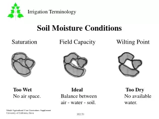
Project Recap: • Soil Moisture – agricultural, hydro-geological modeling and corrections to groundwater gravity measurements. • TDR – time domain reflectometry • VWC – volumetric water content
Principles of TDR Explanation of “Relative Permittivity”: Maxwell: Applications of Relative Permittivity: Ledieu Equation for VWC:
Horizontally Oriented Soil Moisture Sensor Probes • Proven technology • Very accurate VWC measurement • Little or no calibration required • Destructive to soil • In situ TDR device required • Costly • Limited sample volume per probe
Development of a Vertically Oriented TDR Probe System • Challenges: • Calibration of probe connectors • Larger sample volume • Average VWC over several layers v. local measurement at each layer • Unknown soil constituents may deflect probe installation (i.e. buried stones) • Best material for waveguides • Possible Advantages: • Easy installation • Cost effective • Fewer TDR devices required to survey a large land area. Especially when less frequent measurements are needed.
First Attempt!! • Results: • 38% error!! • Interesting variations in pulse reflection from connectors • Probe calibration needed • Probe connector offset constant needed
Calibration Method • 20 probe pairs used • 4 pairs @ lengths: 28, 24, 20, 16 and 8 in. • TDR measurements made in air and DI water • 2 measurements made with each pair of waveguides in each medium with each connector • 160 TDR measurements total made • Relative permittivity of water and air known • Measurements compared with theoretical values • Probe constant isolated empirically
Results of Calibration • Electrical path length constant of waveguide connectors was used to correct previous data collected • Average % error decreased by nearly 32%
What’s Next • Develop a field ready model • Further test existing and new probes and connectors in a wider variety of conditions • Implement a comprehensive soil moisture system around gravity measurement sites • Use reliable soil moisture information to correct gravity ground water measurements