Introduction to Hardware Description Languages (HDLs) and Their Applications in Digital Design
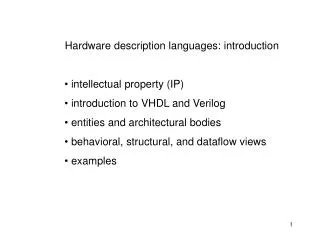
Hardware Description Languages (HDLs) have revolutionized the way digital circuits are designed by providing a textual representation that facilitates readability and simulation. Originating in the 1970s and 1980s, popular HDLs like VHDL, Verilog, and SystemC allow designers to convey complex circuit behaviors without relying solely on graphical schematics. This introduction covers the essential features of HDLs, including description of components, simulations with testbenches, and practical examples such as defining OR gates, full adders, and FSMs, making HDLs crucial for contemporary digital design.


Introduction to Hardware Description Languages (HDLs) and Their Applications in Digital Design
E N D
Presentation Transcript
Introduction • A drawing of a circuit, or schematic, contains graphical information about a design • Inverter is above the OR gate, AND gate is to the right, etc. • Such graphical information may not be useful for large designs • Can use textual language instead D oorOpener c f h p a tap a si r t n o c o t g
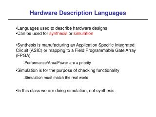
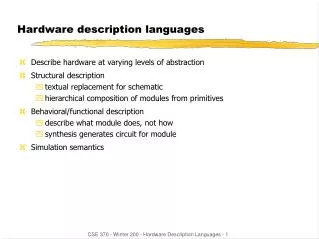
Computer-Readable Textual Language for Describing Hardware Circuits: HDLs • Hardware description language (HDL) • Intended to describe circuits textually, for a computer to read • Evolved starting in the 1970s and 1980s • Popular languages today include: • VHDL –Defined in 1980s by U.S. military; Ada-like language • Verilog –Defined in 1980s by a company; C-like language • SystemC –Defined in 2000s by several companies; consists of libraries in C++
Describing Combinational Behavior in VHDL • Describing an OR gate's behavior • Entity defines input/output ports • Architecture • Process – Describes behavior • Behavior assigns a new value to output port F, computed using built-in operator "or" library ieee; use ieee.std_logic_1164.all; entity is OR2 port in (x, y: std_logic; out F: std_logic ); end OR2; architecture of is behavior OR2 begin process (x, y) begin or F <= x y; end process ; end behavior; • Describing a custom function's behavior • Desired function: f = c'*(h+p) architecture of is beh DoorOpener begin process (c, h, p) begin not and or f <= (c) (h p); end process ; end beh;
Testbenches • Testbench • Assigns values to a system's inputs, check that system outputs correct values • A key use of HDLs is to simulate system to ensure design is correct Testbench Set input values, check output values SystemToTest
Testbench Set input values, check output values SystemToTest Testbench in VHDL • Entity • No inputs or outputs • Architecture • Declares component to test, declares signals • Instantiates component, connects to signals • Process writes input signals, checks output signal • Waits a small amount of time after writing input signals • Checks for correct output value using "assert" statement DoorOpener1 process
a b ci Full adder s c o Describing a Full-Adder in VHDL • Entity • Declares inputs/outputs • Architecture • Described behaviorally (could have been described structurally) • Process sensitive to inputs • Computes expressions, sets outputs s = a xor b xorci co = bc + ac + ab
a3 b3 a2 b2 a1 b1 a0 b0 ci a b ci a b ci a b ci a b ci F A F A F A F A c o s c o s c o s c o s c o s3 s2 s1 s0 Describing a Carry-Ripple Adder in VHDL • Entity • Declares inputs/outputs • Uses std_logic_vector for 4-bit inputs/outputs • Architecture • Described structurally by composing four full-adders (could have been described behaviorally instead) • Declares full-adder component, instantiates four full-adders, connects • Note use of three internal signals for connecting carry-out of one stage to carry-in of next stage co1 co2 co3
Describing a 4-bit Register in VHDL • Entity • 4 data inputs, 4 data outputs, and a clock input • Use std_logic_vector for 4-bit data • I: in std_logic_vector(3 downto 0) • I <= "1000" would assign I(3)=1, I(2)=0, I(1)=0, I(0)=0 • Architecture • Process sensitive to clock input • First statement detects if change on clock was a rising edge • If clock change was rising edge, sets output Q to input I • Ports are signals, and signals store values – thus, output retains new value until set to another value
4-bit up-counter c n t ld 4-bit register 4 4 +1 4 4 t c C Describing an Up-Counter in VHDL tempC • Described structurally (could have been described behaviorally) • Includes process that updates output port C whenever internal signal tempC changes • Need tempC signal because can't read C due to C being an output port
Describing an Oscillator in VHDL • Entity • Defines clock output • Architecture • Process • Has no sensitivity list, so executes non-stop as infinite loop • Sets clock to 0, waits 10 ns, sets clock to 1, waits 10 ns, repeats
Inputs: b; Outputs: x x=0 Off b ’ b x=1 x=1 x=1 On1 On2 On3 Describing a Controller in VHDL FSM inputs x b FSM outputs Combinational logic n1 n0 s1 s0 State register clk • FSM behavior captured using architecture with 2 processes • First process models state register • Asynchronous reset sets state to "S_Off" • Rising clock edge sets currentstate to nextstate • Second process models combinational logic • Sensitive to currentstate and FSM inputs • Sets FSM outputs based on currentstate • Sets nextstate based on currentstate and present FSM input values • Note declaration of new type, statetype
Summary • Hardware Description Languages (HDLs) are widely used in modern digital design • Textual rather than graphical language sufficient for many purposes • HDLs are computer-readable • Great for simulation • VHDL, Verilog, and SystemC are popular • Introduced languages mainly through examples • Numerous HDL books exist to teach each language in more detail