Hardware Description Languages: VHDL vs. Verilog Overview
110 likes | 201 Views
Learn about specifying hardware designs, automated processes, design for testability, and more using efficient HDL like Verilog.

Hardware Description Languages: VHDL vs. Verilog Overview
E N D
Presentation Transcript
Hardware Description Language B. Ramamurthy
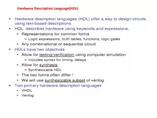
HDL • How do you specify this hardware design or model, its components/modules, instances and interface (ports) to the external world? • How to automate the process? • How do you design for testability/verifyability? • Using a language that we can easily specify and understand. • VHDL is a older language • Verilog is commonly used
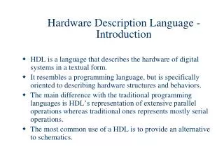
HDL (contd.) • The principal feature of a hardware description language is that it contains the capability to describe the function of a piece of hardware independently of the implementation. • The great advance with modern HDLs was the recognition that a single language could be used to describe the function of the design and also to describe the implementation. • This allows the entire design process to take place in a single language, and thus a single representation of the design.
Verilog • The Verilog Hardware Description Language, usually just called Verilog, was designed and first implemented by Phil Moorby at Gateway Design Automation in 1984 and 1985. • Verilog simulators are available for most computers at a variety of prices, and which have a variety of performance characteristics and features. • Verilog is more heavily used than ever, and it is growing faster than any other hardware description language. • It has truly become the standard hardware description language.
Verilog • A Verilog model is composed of modules. A module is the basic unit of the model, and it may be composed of instances of other modules. • A module which is composed of other module instances is called a parent module, and the instances are called child modules. system comp2 comp1 sub3
Verilog Design Concept System instantiates comp1,comp2 comp2 instantiates sub3 System comp1 comp2 sub3
Example • Primitives are instantiated in a module like any other module instance. For example, the module represented by this diagram would be instantiated: module example1; wire n1, n2; reg ain, bin; and andMod(n1, ain, bin); not notMod(n2, n1); endmodule ain n2 n1 bin
Solutions using “assign” and “wire” module AOI (input A, B, C, D, output F); /* start of a block comment wire F; wire AB, CD, O; assign AB = A & B; assign CD = C & D; assign O = AB | CD; assign F = ~O; end of a block comment */ // Equivalent... wire AB = A & B; wire CD = C & D; wire O = AB | CD; wire F = ~O; endmodule // end of Verilog code
NetList module DEC1OF8 (X0B, X1B, X2B, X3B, X4B, X5B, X6B, X7B, SL0, SL1, SL2, ENB); output X0B, X1B, X2B, X3B, X4B, X5B, X6B, X7B; input SL0, SL1, SL2, // select signals ENB; // enable (low active) //Module Description not // invert SL0-SL2, N1 (sl0b, SL0), // & ENB N2 (sl1b, SL1), N3 (sl2b, SL2), N4 (enbb, ENB); nand // select outputs NA1 (X0B, sl2b, sl1b, sl0b, enbb), // (low active) NA2 (X1B, sl2b, sl1b, SL0, enbb), NA3 (X2B, sl2b, SL1, sl0b, enbb), NA4 (X3B, sl2b, SL1, SL0, enbb), NA5 (X4B, SL2, sl1b, sl0b, enbb), NA6 (X5B, SL2, sl1b, SL0, enbb), NA7 (X6B, SL2, SL1, sl0b, enbb), NA8 (X7B, SL2, SL1, SL0, enbb); endmodule
Module Definition + Gate Level Diagram module abc (a, b, c, d, s1, s0); input s1, s0; output a, b, c,d; not (s1_, s1), (s0_, s0); and (a, s1_, s0_); and (b, s1_, s0); and (c, s1, s0_); and (d, s1, s0); endmodule