Download
1 / 22
220 likes | 237 Views
This project aims to create a brain-mimicking phantom for 7T MRI imaging, matching brain tissue properties and structure. Methods include measuring relaxivity with GdCl3, fabricating a concentric phantom, and mimicking CSF. Results show successful design with similar dielectric properties, anatomical structure, tissue contrast, and relaxation times as human brain tissue imaged at 7T. The phantom allows for RF power deposition measurement and RF shimming optimization.

E N D
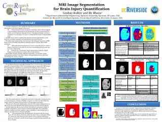
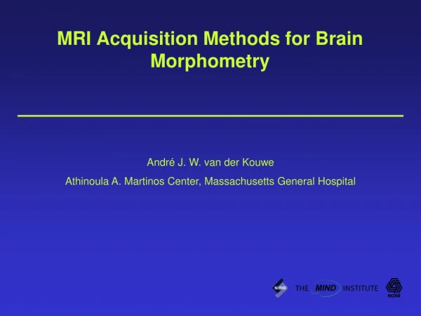
Brain Phantoms for Ultra High Field MRI Six-week project Lauren Villemaire MBP 3970Z Department of Medical Biophysics University of Western Ontario
Outline • Introduction MRI Imaging at high magnetic fields Phantoms • Objective • Methods • Results • Discussion • Conclusion • Acknowledgements • References
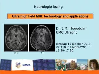
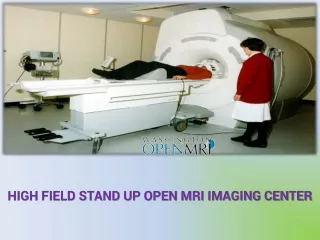
Introduction to MRI • Uses nuclear magnetic resonance of protons to produce proton density images • Magnetism - proton spin • Larmor Frequency - rate of precession The 7T MRI at Robarts Research Institute.
The primary magnet - main magnetic field - the tesla • The gradient magnet - alters magnetic field - focuses magnetic field • The RF coil - alters direction of proton spin - detects precession energy • T1 and T2 relaxation times - characteristic of tissues - image contrast
Imaging at ultra high magnetic fields Disadvantages RF heterogeneities Magnetic susceptibility artifacts Specific Absorption Rate (SAR) Advantages SNR Spatial Resolution Tissue Contrast
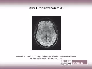
Human hippocampus Images at 7T have much higher spatial resolution and SNR than at 1.5T Brain images at 7T have shading and bright spots that compromise image homogeneity. 1.5 T 7 T
What are phantoms? An artificial object of known size and composition that is imaged to test, adjust or monitor an MRI system’s • homogeneity • imaging performance • orientation aspects.
Objective • To develop a brain-mimicking phantom for use in the 7T MRI with the following characteristics in common with the brain: - Grey matter/white matter T1 and T2 relaxation times - Electrical and wave properties - Anatomical structure and size (not symmetrical)
Method The relaxivity of varying concentrations of GdCl3 and agarose were measured A concentric phantom was fabricated Coil loading was measured and B1+ effects were empirically determined CSF • T1 and T2 values that match average human grey matter and white matter values were determined via measurements done by MRI • CSF was mimicked by a 50-mM NaCl solution White matter Grey matter
Axial images of brain slices were obtained from Brain Web – Simulated Brain Database. These images represent the standard size and structure of the human brain. Number of slices 36 Modality T1 Slice thickness 5mm Noise 0% Intensity non-uniformity (RF) 0%
14 brain slices, each 1cm apart, were selected Images were, then, modified using Image J to sharpen and enhance contrast between grey matter, white matter, and CSF.
Each image was manually outlined to distinguish between the different compartments.
Tracings were scanned and made binary using ImageJ and then converted to SAT using Solid Works. jpg pdf dxf sat
Images were then formatted to open in the MasterCam Mill 9 program where they were modified.
Results An agarose gel and saline solution phantom was developed to mimic properties of the human brain for imaging at 7T.
TI = 500ms T1 = 1400ms to null GM T1 = 900ms to null WM T1W MP RAGE images of the same slice of the phantom with different inversion times.
Comparison of RF interference patterns. Single element transmitting (located at back of head) All elements transmitting with random phases to produce interferences.
Now that each brain slice is compartmentalized into MasterCam, they can be milled out of plastic and eventually filled with the appropriate brain mimicking substances.
Discussion I’ve successfully designed a head-mimicking phantom for use in the 7T MRI. • The phantom exhibits very similar dielectric properties (conductivity and permittivity) to the human brain • The phantom is the same size and shape of the average brain • The phantom has similar anatomical structure to the average brain • The phantom has grey matter/ white matter contrast with the same T1 and T2 relaxation times as human brain tissue imaged at 7T
Conclusion Such a phantom is unique. It would... (1) allow the ability to instrument the phantom and measure RF power deposition (SAR) and (2) optimize RF shimming techniques using multiple transmitters. Both of these are major challenges currently.
Acknowledgements Supervisor: Dr. Ravi S. Menon Post-doctoral student: Kyle Gilbert Graduate student: Andrew Curtis
References • Brain Web: Simulated Brain Database http://mouldy.bic.mni.mcgill.ca/brainweb/ • Rooney WD, et al. MagnReson Med 2007; 57:308-318 • Wright PJ et al. MAGMA 2008; 21:121-130 • Yoshida A et al. Int J Hyperthermia 2004; 20:803-814