Download
1 / 16
160 likes | 182 Views
Learn about driven, damped harmonic oscillators with real-life examples, frequency representations, Fourier series, and LRC circuit investigations. Understand the concepts of natural and driving frequencies, resonance, and quality factor in oscillatory systems.

E N D
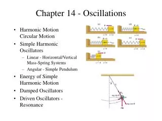
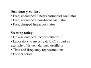
Summary so far: • Free, undamped, linear (harmonic) oscillator • Free, undamped, non-linear oscillator • Free, damped linear oscillator Starting today: • Driven, damped linear oscillator • Laboratory to investigate LRC circuit as example of driven, damped oscillator • Time and frequency representations • Fourier series
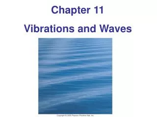
THE DRIVEN, DAMPED HARMONIC OSCILLATOR Reading: Main 5.1, 6.1 Taylor 5.5, 5.6
Natural motion of damped, driven harmonic oscillator viscous medium k F0coswt m k m x Note w and w0 are not the same thing! • is driving frequency w0 is natural frequency
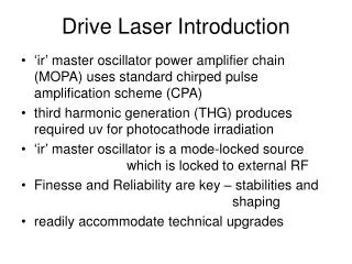
Natural motion of damped, driven harmonic oscillator L I C R Vocoswt Apply Kirchoff’s laws http://www.sciencejoywagon.com/physicszone/lesson/otherpub/wfendt/accircuit.htm
large if b is small compared to w0 underdamped Damping time or "1/e" time is t = 1/b > 1/w0(>> 1/w0 if b is very small) How many T0 periods elapse in the damping time? This number (times π) is the Quality factor or Q of the system.
L I C Q factor: R Natural (resonance) frequency determined by the inductor and capacitor Damping determined by resistor & inductor LRC circuit LCR circuit obeys precisely the same equation as the damped mass/spring. Typical numbers: L≈500µH; C≈100pF; R≈50W w0≈106s-1 (f0≈700 kHz) t=1/b≈2µs; (your lab has different parameters)
Measure the frequency! Menu off button “push”=enter “ctrl-alt-del” for osc save to usb drive Put cursor in track mode, one to track ch1, one for ch2 measure Vout across R Vin to func gen
V0real, constant, and known Let's assume this form for q(t) But now q0is complex: This solution makes sure q(t)is oscillatory (and at the same frequency as Fext), but may not be in phase with the driving force. Task #1: Substitute this assumed form into the equation of motion, and find the values of |q0| and fqin terms of the known quantities. Note that these constants depend on driving frequency w (but not on t – that's why they're "constants"). How does the shape vary with w?
Assume V0real, and constant Task #2: In the lab, you'll actually measure I (current) or dq/dt. So let's look at that: Having found q(t), find I(t) and think about how the shape of the amplitude and phase of I change with frequency.
Assume V0real, and constant Task #1: Substitute this assumed form into the equation of motion, and find the values of |q0| and f in terms of the known quantities. Note that these constants depend on w (but not on t – that's why they're “constants”). How does the shape vary with w?
"Resonance" Charge Amplitude |q0| Driving Frequency------> Charge Phase fq 0 -π/2 -π
Task #2: In the lab, you’ll actually measure I (current) or dq/dt. So let's look at that: Having found q(t), find I(t) and think about how the shape of the amplitude and phase of I change with frequency.
“Resonance” Current Amplitude |I0| Driving Frequency------> π/2 Current Phase 0 -π/2
“Resonance” Charge Amplitude |q0| w0 Driving Frequency------> Current Amplitude |I0| w0
Charge Phase fq 0 -π/2 -π w0 Driving Frequency------> π/2 Current Phase 0 -π/2 w0