Download
1 / 16
170 likes | 416 Views
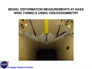
MODEL DEFORMATION MEASUREMENTS AT NASA WIND TUNNELS USING VIDEOGRAMMETRY. AEROELASTIC DEFORMATION MEASUREMENTS. STATE-OF-THE-ART twist due to aero loads main wing element. CURRENT CHALLENGES Components (high lift) flap, gap, and overhang Dynamics: up to 1000 Hz.

E N D
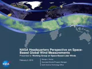
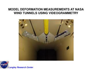
MODEL DEFORMATION MEASUREMENTS AT NASA WIND TUNNELS USING VIDEOGRAMMETRY
AEROELASTIC DEFORMATION MEASUREMENTS STATE-OF-THE-ART twist due to aero loads main wing element • CURRENT CHALLENGES • Components (high lift) • flap, gap, and overhang • Dynamics: up to 1000 Hz
WHAT IS VIDEOGRAMMETRY • Photogrammetry + video image processing • Extraction of 2D or 3D info from 2D image data • 1 camera 3D rigid body or 2D deformation • (1D must be known for 2D deformation) • 2 or more cameras 3D deformation
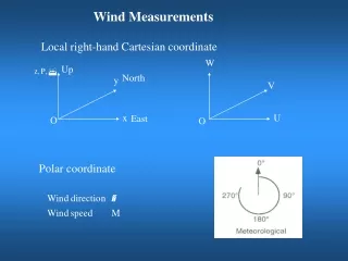
2.5 m VIDEOGRAMMETRIC TECHNIQUE(VMD) NTF test section • Optical targets • Single-camera photogrammetry X, Z computed with Y known • video-rate CCD camera • Frame grabber • Auto target location or tracking • 3-step calibration procedure Looking downstream (+X) Z Y
1 2 3 4 5 6 7 Z Flow X POLISHED PAINT TARGETSNational Transonic Facility Semispan POLISHED PAINT TECHNIQUE • 0.0005 inch (1/2 mil) thickness • Feathered edges (no abrupt steps) • 10 inch surface roughness • Precision templates Full-span
CALIBRATION (1) image plane corrections (2) coordinate system (3) Wind-off polars for angle and X,Z
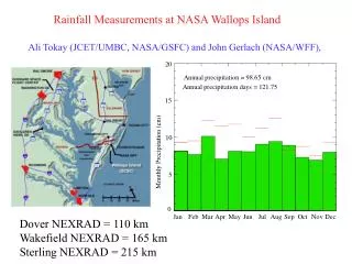
FACILITIES • National Transonic Facility • Transonic Dynamics Tunnel • 16-Ft Transonic Wind Tunnel • Unitary Plan Wind Tunnel • Ames 12-Ft Pressure Tunnel Deformation measurements made from subsonic to supersonic - high lift, cruise, onset of buffet
NATIONAL TRANSONIC FACILITY(NTF) • Cryogenic • High Re high Q • Last 9 tests: deformation
-5 1 2 3 4 5 6 7 Z 24 Flow X VECTOR DISPLACEMENTS
DYNAMIC DEFORMATION OF SEMISPAN MODEL Transonic Dynamics Tunnel Dq, deg Time, sec Inboard f = 10.6 Hz Power Outboard f = 10.6 Hz Power f, Hz
DEFORMATION CONTOURS DZ, inch h = 1 h = 0 D t, sec 0.000 0.017 0.034 0.050 0.067
DZ, inch 0 . 0 8 0 . 0 6 0 . 0 4 0 . 0 2 0 - 0 . 0 2 - 0 . 0 4 - 0 . 0 6 - 0 . 0 8 MICRO AIR VEHICLEDEFORMATION CONTOURS
867 FRAMES/SEC DATA ACQUIREDBASIC AERODYNAMIC RESEARCH TUNNEL
CONCLUDING REMARKS • Videogrammetry useful for static and dynamic aeroelastic measurements in wind tunnels • Single-camera, single-view technique is workhorse • Useful for a number of tests at NASA facilities • National Transonic Facility (last 9 customer tests) • 16-Ft Transonic Wind Tunnel • Transonic Dynamics Tunnel • Unitary Plan Wind Tunnel • Ames 12-Ft Pressure Tunnel • Future efforts • Dynamic measurements up to 1000 Hz • Micro air vehicles • Ultralight and inflatable large space structures • Robustness with and without targets