Download
1 / 9
90 likes | 175 Views
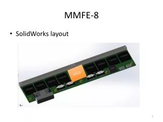
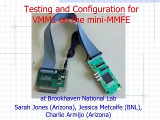
MMFE-8 Requirements. Kenneth Johns University of Arizona. MMFE-8 in SolidWorks. Functions. Accept 8x64 channels of MM input via Zebra connectors and integrated with MM detectors

E N D
MMFE-8 Requirements Kenneth Johns University of Arizona
Functions • Accept 8x64 channels of MM input via Zebra connectors and integrated with MM detectors • Provide a path for L1 Data from the VMM to the Companion ASIC #2 (CA2) where it is buffered pending L1 Accept (L1A) • Provide a path for the VMM Address in Real Time (ART) Data readout to an ART Data Driver Card (ADDC) • Provide a path for VMM L1 Data readout to an L1 Data Driver Card (L1DDC) via the CA2 using an e-link • Provide a path for TTC information and (possibly phase adjusted) BC clock and their distribution to VMM’s using an e-link • Provide a path for VMM and CA2 configuration and readout of VMM and CA2 status information using an e-link • Provide a method for performing charge, time and threshold calibration of the VMM’s • Provide radiation (200 krad) tolerant power (8.3W) to the VMM’s and CA2 and monitoring of this power • Provide cooling for the VMM’s and CA2 and monitoring of this cooling
Interfaces • E-link 1 • L1 Data up and TTC Data down • E-link 2 • Status Data up and Configuration Data down • Custom LVDS links from VMMs to ADDC for ART Data • Custom LVDS links between VMM and CA2 for L1 Data, TTC Data, Configuration Data, and Status Data
Interface Details • L1 Data • Source/Destination: VMM to CA2 Data content: 48 bits • Estimated BW: 460 Mbps from each VMM • Calculation: 15 kHz/cm2/s x 0.04 cm x 50 cm x 64 x 48 bits x 5 strips/hit • ART Data • Source/Destination: VMM to ADDC Data content: 7 bits (6 bits address and 1 bit flag) • Estimated BW: < 320 Mbps (160 MHz DDR) • Calculation: ART readout clock is 160 MHz DDR
Interface Details • L1 Data (e-link up) • Source/Destination: CA2 to L1DDC via e-linkData content: 48 bits plus TBD • Estimated BW: 37 Mbps • Calculation: 100 kHz x 15 kHz/cm2/s x 0.04 cm x 50 cm x 64 x 48 bits x 5 strips x 8 x 100 ns • TTC Data (e-link down) • Source/Destination: L1DDC to CA2 via e-linkData content: One bit (L1A) @ 40 MHz, one bit (other TTC info) using 40 MHz clock • Estimated BW: < 80 Mbps • Calculation: Uses the 40 MHz e-link clock (DDR)
Interface Details • Configuration and Status Data (e-link) • Source/Destination: L1DDC to CA2 via e-linkData content: Configuration data to the CA2 and Status data from the CA2 • Estimated BW: <80 Mbps • Calculation: Uses the 40 MHz e-link clock (DDR)
I/O Connections between CA2 and VMM • L1 Data (4 pairs) • L1 Data clock • SYNCH • L1 Data (d0 and d1) • Configuration (3 pairs) • Configuration clock and di and d0 • TTC (5 pairs) • BC clock (phase adjusted) • L1A (perhaps the next four can be multidrop) • BCR • FER • CAL • Control (2 pairs) • WEN and ENA (perhaps these can be multidrop) • Status (2 pairs) • VMM status • Status clock Implies 16 x 8 = 128 pairs (256 pins) for CA2
Open Issues – Calibration and SCA • For VMM1 • Charge calibration needed external ADC for DAC output (need to determine gain per channel) • Time calibration needed no external ADC • Threshold calibration needed external ADC for global threshold and trimmer adjustment • Open questions • Can we rely on pre-installation bench measurements for DAC output, … ? • How much do these quantities (DAC output, …) vary with time? • Are there other conditions that affect these quantities? • Are there other ways to calibrate without the need for external ADCs?