Download
1 / 40
400 likes | 505 Views
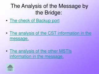
The Analysis of the Message by the Bridge:. The check of Backup port The analysis of the CST information in the message. The analysis of the other MSTIs information in the message. performed for the CST and MSTIs together.

E N D
The Analysis of the Message by the Bridge: • The check of Backup port • The analysis of the CST information in the message. • The analysis of the other MSTIs information in the message.
performed for the CST and MSTIs together. • If the message is from this bridge, the only thing the message is used for is to determine if the port should become a backup port. • The comparison is between: • The cost of the ports • The priority of the ports • The id of the ports
If the message claims the CST root is “worse” than the root the bridge holds – a message is sent and this message is ignored. • The bridge determines port roles for the CST. • Determining whether the bridge has a Master port or not.
Bridge1 Config 1 R R Bridge2 Config 2 Bridge3 Config 2 • The port is a MasterPort: 1) the port is a root port 2) the message is from another region • The port is no longer a Master port: • the port is no longer a root port • the message that changed the port is from the bridge region (the IST root of the Bridge initialized by message) • When a bridge finds out it has a Master Port: • it claims to be the “IST root” of its’ region. • initializes its’ data. • sends a message announcing that the IST root in the region has changed
The bridge checks if the message is not from its’ region • If the message is from outside the region: • The information on the MSTIs is ignored. • If the message is from inside the region: • If the message announces of a new IST root in the region: • the bridge initializes its’ data. • Else: • the bridges determines the port roles for its’ ports in all of the different MSTIs.
The Message class string m_mac int* m_BridgePrio string m_config int m_PortId ROLE* m_PortRoles string* m_root int* m_RootPrio int* m_PathCost string m_ISTroot
string m_mac int m_BridgeId string m_ISTroot string m_BridgeConfig bool m_OutOfRegion string m_OutOfRegionBridge int* m_BackupTo The Port Class int m_PortId ROLE* m_roles int* m_priority Int* m_cost HARDWARE m_ConnectedTo int m_LanId Port* m_port queue<Message> m_NewMsg
The Bridge class string m_name int m_id string m_mac string m_config int m_region int* m_priority int m_NumPorts Port* m_ports string m_ISTroot string* m_RootMac int* m_RootPrio int* m_RootPort int* m_MinCost bool m_MasterPort
The Lan Class int m_LanId int m_PortsNum list<Port*> m_ports
MSTP (802.1s) Multiple Spanning Tree Protocol
Topics • Introduction • What is MSTP. • Benefits of MSTP to previous protocols. • The distributed algorithm • MSTP BPDUs • Port roles • Implementation
Topics (cont.) • The Non-distributed algorithm • How the algorithm finds the network topology and tree • Main parts of the algorithm • Implementation details
Topics (cont.) • The Presenter™ • Overview • Input file (Input.txt) • Parser • Drawing builder • Drawer • User configuration
What is MSTP? • The network divided into regions, each region performs as a super-bridge in the main tree (CST) • Each region contains all interconnected bridges and LANs that have the same MSTP Configuration (a LAN is considered in the same region as the bridge designated on that LAN in MSTI 0) • An alphanumeric configuration name (32 bytes) • A configuration revision number (two bytes) • A 4096-element table that associates each of the potential 4096 VLANs supported to a given instance
What is MSTP? • Inside each region 16 (CISCO) spanning trees are generated and are referred as MSTIs (MST Instances) • MSTI 0 also know as the IST (Internal Spanning Tree). The IST root has a special port that can send frames to other regions (Master Port). • The MSTP BPDU is the regular TSTP BPDU with additional data at its end. The MSTP part of the BPDU will not leave the region (boundary ports will not transmit that part)
Benefits of MSTP to previous protocols • Enables load balancing by forwarding messages on different paths. • Less data to store and “spares” the CPU for each switch. • System administrator can configure better paths for certain connections.
The Data Structures used: • Message class • Port class • Bridge class • Lan class
Main Global Parameters: • A list of Bridges: BridgeList • An array of Lans: LanArray
The Driving Mechanism: • Initializing The Global Parameters By the file argv[1] (user parameter) • Do for every Bridge B • send an “I am root” message on all the designated ports (which are all his ports).
Until there are no changes in the system • For each Bridge B • go through all its’ ports and handle the new messages. • Print the results to argv[2] (user parameter)
Backup Port • A message is received from the bridge itself • Root Port • A message is received with a better root • A message is received with the same root • Designated Port • Initialization • A message with a better path cost to root • A message with the same path cost to root • Alternate Port • The port it not backup, not root port and not designated • The port is a Master Port – in the MSTIs • The port is connected to a LAN or a bridge in a different region
General Idea • General representation of the algorithm • Separating the network into regions. • Reduction to shortest path problem. • Executing Dijkstra algorithm. • Determining spanning tree topology.
Dijkstra • Computes in a graph G=(V,E) shortest paths from a source vertex s to all other vertices in V. We denote the weight of edge (u,v) by Wuv. Let u be a vertex in T so that d[u] is minimum For all
Main parts of implementation • Analyzing the input file. • Adding LANs. • Separating the network into regions (building the CST). • Reduction to Dijkstra. • Dijkstra. • Definingports roles for root and designated ports. • Calculating cost to root per bridge. • Defining port roles. • Writing to GUI. • Repeat for each region and for each MSTI.
Implementation details separating the network into regions: • Creating the CST: the entire network is considered to be one region. • Separating the network into Regions: The root of CST gets 0 as region number. BFS algorithm is applied on the CST tree. • For each Region, a vector of Bridge* is created
Implementation details Reduction to shortest path problem • Every connection between bridge and LAN or between two bridges is converted to two opposite directed arcs. • Each arc directed from bridge to LAN gets the weight of 0. Each arc directed from LAN vertex to bridge vertex gets the weight of the port cost. Each arc directed from bridge vertex to another bridge vertex gets the weight of the port cost of the bridge that is represented by the arc’s end.
Implementation details defining port roles for all • Port that connects father to son in tree is designated, port that connects son to father is root port. • All ports that are not root port nor designated and connect bridge to LAN are back up ports. • All ports that connect two bridges that are in son-father or father-son relation and not signed yet are alternate ports. • For all other yet not-signed ports special condition is checked.
Overview Input file Presenter™ Drawing builder Drawing Instructions Drawer Translator Input.txt Drawing
Input file • Includes bridge information per MSTI • Each bridge record includes: • MAC Address • Name • Region • Port roles per MSTI • 16 MSTIs where MSTI 0 represents the CST • Specifications file included
Parser • Single pass reader • Generates internal tables • Bridge to bridge connections (per MSTI) • Bridge to LAN connections (per MSTI) • Bridge to region mapping • LAN to region mapping • Stores costs and connection types • Stores extra bridge information (i.e. Name)
Drawing Builder • 3 Types of trees • CST • Generated by comparing regions of LANs and bridges on their active connections. • Regional Tree • Generated by reading the connections within a region. • Each bridge and LAN is given a layer in the drawing. • All MSTIs are created. • Super Tree • Generated by disregarding the regions in the Regional Tree algorithm. • Allows viewing the connections between the regions.
Drawing Builder (cont.) • Generates Drawing Instructions • Each MSTI has its own drawing instructions. • Calculated once for each window. • Include information about the default positions of the bridges and the LANs and about the connection types and costs. Also includes bridge information to display.
Drawer • Displays the tree components on screen using the drawing instructions. • Displays various connection types with different colours and styles and writes the costs. • Displays bridge and LAN information as a hint and in the status-bar (pressing Ctrl will show it on the drawing area). • Allows repositioning the tree components (the labels and connections are redrawn automatically to accommodate the changes) • Easy to scroll through MSTIs • Allows comparison of MSTIs, regions and even different topologies.
User configuration • MSTP.ini file • Allows to change to colours of all connection types. • Allows to change the widths of all connection types. • Allows to change the default distance between bridges. • Auto created on startup. • .BMP files • Bridge image is dynamically loaded from bridge.bmp file (root bridge image is loaded from rootbridge.bmp file and it must be the same width and height as the bridge.bmp image). • LAN image is dynamically loaded from lan.bmp file.
Frame received without error on port x Forward frame on the indicated port Calculate frame's VLAN and MSTI no x is the destination port for this message Destination found in forwarding databases Is x blocking on that MSTI? no yes yes no yes Discard frame Send frame on every forwarding port != x (including Master port) Discard frame Frame forwarding algorithm