Download
1 / 20
210 likes | 446 Views
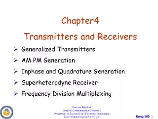
Chapter4 Transmitters and Receivers Generalized Transmitters AM PM Generation Inphase and Quadrature Generation Superheterodyne Receiver Frequency Division Multiplexing. Huseyin Bilgekul Eeng360 Communication Systems I Department of Electrical and Electronic Engineering

E N D
Chapter4 • Transmitters and Receivers • Generalized Transmitters • AM PM Generation • Inphase and Quadrature Generation • Superheterodyne Receiver • Frequency Division Multiplexing Huseyin Bilgekul Eeng360 Communication Systems I Department of Electrical and Electronic Engineering Eastern Mediterranean University
Generalized Transmitters Modulating signal Modulated signal Transmitter Any type of modulated signal can be represented by The complex envelope g(t) is a function of the modulating signal m(t) Example:
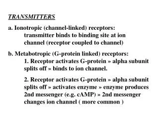
Generalized Transmitters 1. AM- PM Generation Technique: Envelope and phase functions are generated to modulate the carrier as • Two canonical forms for the generalized transmitter: Figure 4–27 Generalized transmitter using the AM–PM generation technique. R(t)and θ(t) are functions of the modulating signal m(t)as given in TABLE 4.1
Generalized Transmitters 2. Quadrature Generation Technique: Inphase and quadrature signals are generated to modulate the carrier as Fig. 4–28 Generalized transmitter using the quadrature generation technique. x(t)and y(t) are functions of the modulating signal m(t)as given in TABLE 4.1
Generalized Receivers • Two types of receivers: Tuned Radio Frequency (TRF) Receiver: Composed of RF amplifiers and detectors. No frequency conversion It is not often used. Difficult to design tunable RF stages. Difficult to obtain high gain RF amplifiers Receivers Superheterodyne Receiver: Downconvert RF signal to lower IF frequency Main amplifixcation takes place at IF
Tuned Radio Frequency (TRF) Receivers Active Tuning Circuit Detector Circuit Bandpass Filter Baseband Audio Amp Local Oscillator • Composed of RF amplifiers and detectors. • No frequency conversion. It is not often used. • Difficult to design tunable RF stages. • Difficult to obtain high gain RF amplifiers
Heterodyning All Incoming Frequencies Fixed Intermediate Frequency Heterodyning (Upconversion/ Downconversion) Subsequent Processing (common)
Superheterodyne Receivers Superheterodyne Receiver Diagram
Superheterodyne Receivers • The RF and IF frequency responses H1(f) and H2(f) are important in providing the required reception characteristics.
Superheterodyne Receivers fIF fIF RF Response IF Response
Image Frequencies Image frequency not a problem. Image frequency is also received