Download
1 / 41
450 likes | 863 Views
Analog Sensors for Motion Measurement. Presented By: Pratyush Singh Naga. C. Pemmaraju Sandeep Panjala Sreenivas Prasanth Bandi March 20, 2006 . CONTENT. Introduction Motion Transducers Variable Inductance Transducers Permanent Magnet Transducers Eddy Current Transducers

E N D
Analog Sensors for Motion Measurement Presented By: Pratyush Singh Naga. C. Pemmaraju Sandeep Panjala Sreenivas Prasanth Bandi March 20, 2006.
CONTENT • Introduction • Motion Transducers • Variable Inductance Transducers • Permanent Magnet Transducers • Eddy Current Transducers • Variable Capacitance Transducers • Piezoelectric Transducers • Other types of Transducers • Design Criterion for Control System • Conclusion
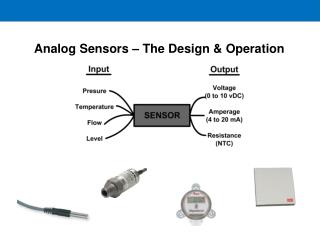
INTRODUCTION Measurement of plant outputs and feedback signals is very important Sub measurement system are used for this purpose and are made up of transducers and sensors and they are used in feedback systems TRANSDUCER: Transducer is a device, that converts one type of energy to another. Transducers are used for compensation in different plants and systems. Help in reducing the sensitivity of a system to parameter change.
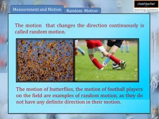
Motion transducers • Motion here means the four kinematics variables Displacement Velocity Acceleration Jerk • Note : That each variable is a time derivation of the preceding one. • Motion measurement is extremely important for system’s or plant proper functioning • The basic working principle of motion transducer have been discussed with illustration examples.
Basic Inductive Displacement Sensor. • Uses the simple principle of mutual inductance. • AC input is applied to coil A & output is measured across B. • Movement of the ferromagnetic core results in inductance from A to B
Linear Variable Differential Transformer. • Used for measurements in the range of mm or cm. • Supply is provided to the middle coil and output is taken across the other two coils. • Differential amplifier is used to measure the differential output from the windings.
Moire Fringe Detector • It converts Light energy to electricity to measure displacement. • Uses two slides with identical patterns and a photocell for the measurement. • Displacement is measured as the amount of light passing through the slides changes
Working principle of Accelerometers • Based on the Principle of F= Ma. • Basic concept of an accelerometer has been shown in the diagram. • Acceleration is measured by calculating the amount of force applied to the restoration spring.
Magnetic Drag For Car Speedometers • Most commonly used technique for speedometers in cars. • Based on the principal of magnetic inductance. • A magnet is connected to the moving shaft and it induces a torque in the stationary disc. • This torque is measured to compute the speed of the cars.
VARIABLE-INDUCTANCE TRANSDUCERS Motion transducers that employ the principle of electromagnetic induction are termed variable-inductance transducers. BASIC PRINCIPLE: When the flux linkage through an electrical conductor changes, a voltage is induced in the conductor. This in turn ,generates a magnetic field that opposes the primary field. If the change in flux linkage is brought about by a relative motion ,the mechanical energy is converted in to electrical energy. DIFFERENT TYPES: 1.Mutual-induction transducers 2.self-induction transducers 3.permanent-magnet transducers
Mutual-induction transducers and Differential Transformers. • The basic arrangement of a Mutual-induction transducer constitutes two coils, the primary and secondary winding. one of the coils carries an AC excitation that induces a steady AC voltage in the other coil • In Mutual-induction transducers, a change in the flux linkage is effected by one of the two common techniques. one technique is to move an object made of ferromagnetic material within the flux path. • The other common way to change the flux linkage is to move one coil with respect to the other.
LINEAR VARIABLE DIFFERENTIAL TRANSFORMER(LVDT) • AN LVDT transducer comprises a coil former on to which three coils are wound. • The primary coil is excited with an AC current, the secondary coils are wound such that when a ferrite core is in the central linear position, an equal voltage is induced in to each coil. • The secondary are connected in opposite so that in the central position the outputs of the secondary cancels each other out.
LVDT contd… • The excitation is applied to the primary winding and the armature assists the induction of current in to secondary coils. • When the armature is in the central position there is an equal voltage induced in to both secondary coils. The sum of secondary outputs cancels each other out resulting in a zero output. • As the armature moves in to sec.1,the result is that sum of sec1 and sec2 favors sec1. • As the armature moves in to sec2,the sum favors sec2. • The out put is an AC waveform .
Contd… • Signal conditioning associated with differential transformers includes filtering and amplification
POTIENTIOMETERS • The potentiometer is a displacement transducer. • The active transducer consists of resistive material whose resistance is proportional to its length. • A fixed voltage is applied across the coil using an external voltage supply. • The output signal is the DC voltage between the movable contact sliding on the terminal of the coil. • Slider displacement x is proportional to the output voltage
Self Induction Transducers • Based on the principle of self induction. • Only a single coil is employed. • Self Induction transducers are usually variable-reluctance devices. • This can be used as a displacement sensor.
Self Induction Transducers Contd.. Self Induction proximity sensor
Permanent Magnet Transducers • A permanent magnet is used to generate a uniform and steady magnetic field. • Permanent magnet transducers are used in measuring speed. • Two types of speed are measured. • Rectilinear speed • Rectilinear velocity transducer is used to measure rectilinear speed. • Angular speed. • DC tachometer-generator and AC tachometer-generator are used in measuring angular speed.
Permanent Magnet Transducers Contd.. Rectilinear velocity transducer
Permanent Magnet Transducers Contd.. DC Tachometer-generator
Permanent Magnet Transducers Contd.. • AC Permanent magnet Tachometers • Contains a permanent magnet rotor and 2 sets of stator windings. • One set of stator windings is energized using AC reference voltage and the other set of windings is used to measure output. • When • Rotor is stationary => output is a constant voltage. • Rotor is moving at finite speed => induced voltage proportional to speed is generated at secondary winding.
Permanent Magnet Transducers Contd.. • AC Induction Tachometers • Similar in construction to two-phase induction motors. • Stator arrangement is similar to AC permanent magnet tachometer and rotor windings are shorted and not energized by any external source. • Voltage is induced in rotor windings which has 2 components, one due to the transformer action of AC supply and the other due to the speed of rotation of rotor. • Voltage induced in the output stator windings is due to both the primary stator winding and rotor winding.
Eddy Current Transducers • Eddy current: • The current generated when a conducting medium is subjected to fluctuating magnetic field. • Eddy currents are circular induced currents generated by an AC current in the nearby coil. • Eddy currents generate their own magnetic fields. • This principle is used in Eddy current proximity sensor.
Eddy Current Proximity Sensor Contd.. Schematic diagram of eddy current proximity sensor
Variable Capacitance Transducer VARIABLE CAPACITOR: Capacitance may be changed either mechanically or electronically. Capacitance: C= KA/x. The variable capacitance used to convert a physical phenomena into electrical signals is called a Variable Capacitance Transducer. Example: capacitor microphone.
Variable Capacitance TransducerContd.. • Capacitance transducers are commonly used to measure small transverse displacements, large rotations, fluid levels and angular velocities. • Capacitive rotation sensor: The angular displacement of one of the plates causes a change in A.
Variable Capacitance TransducerContd.. • Capacitive Displacement Sensor: In this a transverse displacement of one of the plates changes x.
Variable Capacitance TransducerContd.. • Capacitive Liquid level sensor: • A change in k is produced as the fluid level between the capacitor plates changes. • The advantage of capacitance transducer is negligible loading effects. • The capacitance bridge compensates the errors.
Piezoelectric Transducers • Piezoelectricity is the electricity produced by applying pressure. • Piezoelectric materials: Barium titanate, single crystal quartz. • Piezoelectric Effect: • When mechanical stress or strain is applied to the piezoelectric material, generates an electric charge and associated potential difference. • The direct application of piezoelectric effect is used in pressure and strain measuring devices
Piezoelectric Sensor • It may be represented as a charge source with a series capacitive impedance Z. • Z = 1/jwc • Piezoelectric sensors have a limitation on the useful lower frequency.
Piezoelectric accelerometer • Accelerometers are acceleration measuring devices. • The piezoelectric accelerometer is a piezoelectric motion transducer. • It is based on d’ Alembert’s principle which states that • “ If a force of magnitude Ma were applied to the accelerating mass in the direction opposing the acceleration, then the system could be analyzed using static equilibrium considerations.” • Advantage: Light weight and High frequency response.
Piezoelectric accelerometer Contd… • Piezoelectric velocity transducer: • It uses piezoelectric accelerometer and an integrating amplifier along with impedance matching amplifier. • Piezoelectric displacement transducer: • It is obtained by using a double integration of piezoelectric accelerometer.
OTHERS TYPES OF SENSOR Fiber optic sensors and lasers Fiber optic Position sensor Fiber Optic Gyroscope Ultrasonic Sensors Gyroscopic sensors
Fiber optic sensors and lasers • The Characteristic component in a fiber optic sensor is a bundle of glass fiber (Typically a few hundred ) that can carry light. • Basically Two types fiber optic sensors • Indirect type : the optical fiber acts only as the medium in which sensed light is transmitted . In this type the sensing element itself does not consists of optical fibers. Ex: Fiber Optic motion sensor and Tactile sensor . • Direct type: The optical fiber bundle acts as sensing element. When the conditions of the sensed medium change, the light propagation properties of the optical fiber change, providing a measurement of the change in conditions. Ex: Fiber optic gyroscope and fiber optic hydrophones
Fiber optic Position sensor • The Optical fiber bundle is divided into two groups. • Transmitting fiber • Receiving fiber • Light from the light source is transmitted along the first bundle of fibers to the target object whose position is being measured. Light reflected onto the receiving fibers by the surface of the target object is carried to a photo detector. The intensity of the light received by the photo detector will depend on position x of the target object.
Fiber Optic Gyroscope • This is an angular speed sensor that uses fiber optics. • Two loops of optical fibers wrapped around a cylinder are used in this sensor. • One loop carries a monochromatic light (or laser) beam in the clockwise direction, Other loop carries a beam from the same source in counter clockwise direction. Since the laser beam traveling in the direction of rotation of the cylinder has a higher frequency than that of the other beam, the difference in the frequencies of the two lasers beams received at a common location will measure the angular speed of the cylinder. Angular displacement can be measured with the same sensor simply by counting the number of cycles and clocking fractions of the cycles. Acceleration can be determined by digitally determining the rate of change of speed.
Ultrasonic Sensors • In distance measurement using ultrasonic, aburst of ultrasound is projected at the target object, and the time taken for the echo to be recived is clocked. A signal processor computes the position of the target object ,possibly compensating for environmental conditions . alternatively velocity of the target object can also be measured, using the Doppler effect, by measuring the change in frequency between the transmitted wave and the received wave.
DESIGN CRITERION FOR CONTROL SYSTEM • Accuracy is affected by parameter changes in the control system components and by the influence of external disturbances • Consider general feedback control system to parameter changes and to external disturbances. • GP(s) = Transfer function of the plant ( Of the system to be controlled) • G c(s) = Transfer function of the controller ( Including Compensators) • H(s) = Transfer function of the output feedback system ( Including the measurement system) • u = System input command • ud = External disturbance input • y= system output
Contd.. After analyzing the feedback back control system we can stipulate the fallowing design criterion for the system. • Make the measurement system (H) very accurate and stable • Increase the loop gain to reduce the sensitivity of the control system to changes in the plant and controller . • Increase the gain of Gc H to reduce the influence of external disturbances
Conclusion • Analog Transducers play a very important part in insuring proper functioning of the systems. • They are simple, User friendly and reliable. • But with increase in complexity and need for accuracy in modern day plants use of analog transducers is very limited. Newly developed Digital and Optical Transducers are more apt for use in these plants.