Download
1 / 13
150 likes | 589 Views
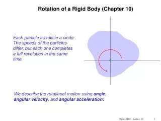
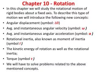
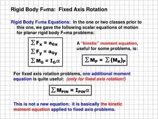
Rigid Body F=ma: Fixed Axis Rotation. Rigid Body F=ma Equations: In the one or two classes prior to this one, we gave the following scalar equations of motion for planar rigid body F=ma problems:. A “kinetic” moment equation , useful for some problems, is:.

E N D
Rigid Body F=ma: Fixed Axis Rotation Rigid Body F=ma Equations: In the one or two classes prior to this one, we gave the following scalar equations of motion for planar rigid body F=ma problems: A “kinetic” moment equation, useful for some problems, is: For fixed axis rotation problems, one additional moment equation is quite useful: (only for fixed axis rotation!) This is not a new equation; it is basically the kinetic moment equation applied to fixed axis problems.
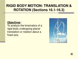
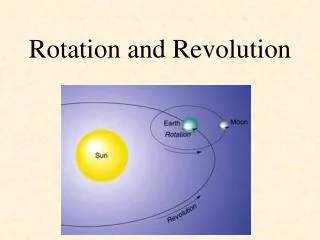
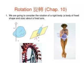
Two types of Problems: (1) G at pin, or (2) G not at pin. In the previous section we discussed translation problems, which had some aG of the mass center, but their angular acceleration a was zero because they did not rotate. This section discusses fixed axis rotation problems which all have an angular acceleration, a, but may or may not have an aG, depending on the location of their mass center G. There are two classes of fixed axis problems, depending on the location of the mass center, G: (1) If G is at the pin, G doesn’t move, and aG is zero. (2) If G is not at the pin, G moves in a circle about the pin, and is thus resolved into aGt and aGn components.
Two types of Problems: (a) G at pin, or (b) G not at pin. There are two classes of fixed axis problems, depending on the location of the mass center, G: (1) If G is at the pin, G doesn’t move, and aG is zero. (2) If G is not at the pin, G moves in a circle about the pin, and is thus resolved into aGt and aGn components.
Where does the SMpin = Ipina equation come from? Consider a basic fixed axis problem, a slender bar, with G not at the pin. Find a and aG.
To review, this is not a radically new equation. It comes from combining: (a) Kinetic moment equation, (b) at = ar, and (c) Parallel axis theorem. Finally, we applied this to a slender bar, but it applies to any shaped body rotating about a pin with its center of mass G not at the pin. If you have a composite body made up of several mass shapes rotating about the pin, you may use this equation as well, where Ipin is the sum of the Ipin’s for all of the mass centers, using the parallel axis theorem: For a composite body: Ipin = S(IG + md2)
Examples where G is not at the pin. Unbalanced rotating equipment is a common, simple example of fixed axis rotation with the mass center not exactly at the pin. Here are some examples: 1. Washing machine: When washing clothes, have your wet clothes shifted to one side of the drum? On the spin cycle, what happens? The entire machine shakes dramatically, doesn’t it? Why? The composite mass center of the drum plus the clothes has shifted well away from the axis of rotation. 2. Automobile tires: Are you aware that tires—even new ones—are not perfectly balanced? When you buy new tires, after they are mounted on your rims, the mechanic balances the rim-tire assembly on a special balancing machine. The machine spins the tires (measuring dynamic loads) and computes the specific locations on the rim to clip on lead weights of various sizes to balance the tire.
Examples where G may or may not be at the pin. 3. Automobile crankshafts: Special care is taken to use counter weights to balance these. 4. Fishing reels: Next time you are in the fishing section at a sporting good store, try out a spinning reel (the kind with an open view of the fishing line). The spool, bale and handle rotate on different axes, but together, they are balanced amazingly well. 5. In-class example: Create a 6-10 inch diameter wooden disk (or an 8 inch long stick) with a centered ¼ inch hole and two off-center holes. Place a ¼ inch bolt, tightened with a nut and washers, in the centered hole. Chuck this in a cordless drill and spin the assembly. The drill should not vibrate very much. Place a bolt and nut in one of the other holes, tighten it, and spin the drill again. Try various speeds. The drill vibrates in your hand. What you are feeling is the rotating force at the drill’s chuck needed to keep the mass center G moving in the circle.
A Disk in a Horizontal Plane: G not at the pin. On rotating equipment, an off-centered G creates a rotating (normal) force component at the pin, with An = m(w2r). Example: A motor drives an unbalanced disk in a HORIZ plane at a constant angular velocity, w. Find the pin reaction at A.
A Disk in a Vertical Plane: G not at the pin. On rotating equipment, an off-centered G creates a rotating (normal) force component at the pin, with An = m(w2r). Example: A motor drives an unbalanced disk in a VERTICAL plane at a constant angular velocity, w. Find the pin reaction at A.