Compact Optics Layout for Beam Compression EOS Setup
Efficiently set up telescope, delay stage, polarizer, and more near the compressor. Place EOS and timing detectors south of the beamline with a flexible approach to bypass existing equipment.

Compact Optics Layout for Beam Compression EOS Setup
E N D
Presentation Transcript
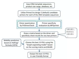
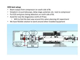
EOS test setup • Beam output from compressor on south side of BL • Simplest is to put telescope, delay stage, polarizer, etc. next to compressor • Put EOS and gross timing detectors on north side of BL • Avoid for now the diagnostics north of IP box • Will try find the best way around this when planning AC experiment • We have flexible solution to work around other installed equipment Already packed CCD & UPD Area for EOS input, delay stage, etc. Compressor Box
EOS setup updated Lens&UPD Analyzer λ/4plate CCD BS II DS II GaP/OTR Polarizer λ/2 plate periscope DS I periscope telescope BS I