Download
1 / 43
430 likes | 577 Views
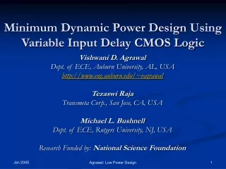
Variable Input Delay CMOS Logic for Low Power Design. Tezaswi Raja Transmeta Corp., San Jose, CA, USA Vishwani D. Agrawal Dept. of ECE, Auburn University, AL, USA http://www.eng.auburn.edu/~vagrawal Michael L. Bushnell Dept. of ECE, Rutgers University, NJ, USA

E N D
Variable Input Delay CMOS Logic for Low Power Design Tezaswi Raja Transmeta Corp., San Jose, CA, USA Vishwani D. Agrawal Dept. of ECE, Auburn University, AL, USA http://www.eng.auburn.edu/~vagrawal Michael L. Bushnell Dept. of ECE, Rutgers University, NJ, USA Research Funded by: National Science Foundation Raja et al.: Low Power Design
Talk Outline • Motivation • Background on Glitch Elimination Techniques • Problem Statement • New Variable Input Delay Logic • Transistor Level Design of Variable Input Delay Gate • Results • Physical Level Implementation • Conclusion and Future Work Raja et al.: Low Power Design
Delay =1 2 2 What Are Glitches? • Glitches occur due to differential (unbalanced) path delays. • Glitches are transients that are unnecessary for the correct functioning of the circuit. • Glitches waste power in CMOS circuits. Delay = 2 Raja et al.: Low Power Design
Prior work • Delay Balancing for Glitch Elimination: • Balancing delays by adding buffers on select paths. • Ref: Chandrakasan and Brodersen and other books • Hazard Filtering for Glitch Elimination: • Glitch suppression by increasing the inertial delay of gates. • Ref: Agrawal et al., VLSI Design `97, `99, `03, `04. • Gate Sizing for Glitch Elimination: • Every gate is modeled as an equivalent inverter. • Model is non-linear • Ref : Berkelaar et al.,IEEE Trans. on Circuits and Systems ‘96 • Transistor Sizing for Area-Speed Oprimization: • Size the width and length of every transistor to get exact delay. • Model is non-linear • Convergence problems due to large search space. • Ref: Fishburn et al.,ICCAD ’85. Raja et al.: Low Power Design
Example: Why Buffers Were Necessary? • Delay unit is the smallest delay possible for a gate in a given technology. • Critical Path is the longest delay path in the circuit and determines the speed of the circuit. 1 Critical path delay = 3 1 1 Raja et al.: Low Power Design
Example (cont.) 0 • For glitch free operation of first gate: • Differential delay at inputs < inertial delay • OK 1 0 1 time 1 Raja et al.: Low Power Design
Example (cont.) 1 1 1 0 1 time • For glitch free operation of second gate: • Differential delay at inputs < inertial delay • OK (Assuming equality does not produce a glitch) Raja et al.: Low Power Design
Example (cont.) 1 time 1 2 1 0 • For glitch free operation of third gate: • Differential delay at inputs < inertial delay • Not true for gate 3 Raja et al.: Low Power Design
Example (cont.) 1 time 1 2 1 1 1 • For glitch free operation with no IO delay increase:Must add a delay buffer. • Buffer is necessary for conventional gate design – only gate output delay is controllable. Raja et al.: Low Power Design
Controllable Input Delay Gates 1 time 1 2 1 2 0 • Assume gate input delays to be controllable • Glitches can be suppressed without buffers Raja et al.: Low Power Design
Problem Statement • Find a glitch reduction technique such that: • All glitches are eliminated in the circuit. • No delay buffers are inserted in the circuit. • Circuit operates at the highest possible speed permitted by the device technology. • Technique should be scalable for large circuits. • Circuits are realizable at the physical level of design. Note: The objective is to minimize switching power. Hence, no attempt is made to reduce short-circuit and leakage power, which is an order of magnitude lower for present CMOS technologies; those components of power may be addressed in the future research. Raja et al.: Low Power Design
I/O path delay through a gate = Input Delay + Output Delay New Variable Input Delay Logic • Output Delay • Propagation delay through a gate from the inputs to the outputs. • Input Delay • Extra delay that can be added on a single I/O path through the gate, which can be controlled independently of the other input delays. • Variable Input Delay Logic • Logic level design of circuits using components with variable input and output delays along different I/O paths through the gate. Raja et al.: Low Power Design
Delay Model for a New Gate • Separate the output (inertial) and input delay variables. • d3 - output delay of the gate. • d3,1- input delay of the gate along path from 1 to 3. • Technology constraint: • 0 d3,1 ,d3,2 ub • Input delay difference has an upper bound, which we define as Gate Input Differential Delay Upper Bound ( ub ). d3,1 + d3 1 3 d3,2 + d3 2 Raja et al.: Low Power Design
Gate Input Differential Delay Upper Bound (ub) • It is a measure of the maximum difference in delay of any two I/O paths through the gate, that can be designed in a given CMOS technology. • Arbitrary input delays cannot be realized in practice due to the technology limitation at the transistor and layout levels. • The bound ub is the limit of flexibility allowed by the technology to the designer at the transistor and layout levels. • The following feasibility condition must be imposed while determining delays for glitch suppression: 0 di, j ub Raja et al.: Low Power Design
New Linear Programs • We propose two new LPs for designing circuits based on the specifications of the design. • Minimum dynamic power (MDP) LP • Where the circuit consumes least power possible and operates at the highest possible speed for that power. • Delay specification (DS) LP • Where the circuit meets a given delay requirement but does it by adding the smallest number of buffers. Raja et al.: Low Power Design
New MDP LP Example 5 d5,1 + d5 1 d7,5 + d7 d5,2 + d5 7 2 d7,6 + d7 d6,2 + d6 d7,4 + d7 3 d6,3 + d6 6 4 • Gate inertial delay variables d5 ..d7 • Gate input delay variables di, j for every path through gate i from input j • Corresponding window variables t5 ..t7 and T5 ..T7. Raja et al.: Low Power Design
New MDP LP Example (cont.) d5,1 + d5 5 1 d7,5 + d7 7 d5,2 + d5 2 d7,6 + d7 d6,2 + d6 d7,4 + d7 6 3 d6,3 + d6 4 • Inertial delay constraint for gate 5: d5 1 • Input delay (feasibility) constraints for gate 5: • 0 d5,1 ub • 0 d5,2 ub Raja et al.: Low Power Design
New MDP LP Example (cont.) d5,1 + d5 5 1 d7,5 + d7 d5,2 + d5 7 2 d7,6 + d7 d6,2 + d6 d7,4 + d7 6 3 d6,3 + d6 4 • Differential delay constraints for gate 5: T5> T1 + d5,1 + d5; t5< t1+ d5,1 + d5; d5 > T5 – t5; T5> T2 + d5,2 + d5; t5< t2+ d5,2 + d5; Raja et al.: Low Power Design
New MDP LP Example (cont.) d5,1 + d5 1 5 d7,5 + d7 d5,2 + d5 7 2 d7,6 + d7 d6,2 + d6 d7,4 + d7 6 3 d6,3 + d6 4 • IO delay constraint for each PO in the circuit: T7maxdelay; maxdelay is the parameter which gives the delay of the critical path. This determines the speed of operation of the circuit. Raja et al.: Low Power Design
New MDP LP Example (cont.) 5 d5,1 + d5 1 d7,5 + d7 7 d5,2 + d5 2 d7,6 + d7 d6,2 + d6 d7,4 + d7 6 3 d6,3 + d6 4 • Objective Function: minimizemaxdelay; • This gives the fastest possible, minimum dynamic power consuming circuit, given the feasibility condition for the technology. Raja et al.: Low Power Design
Solution Curves Power Previous solutions New MDP LP solutions Power consumed by buffers ub= ∞ ub=5 ub=0 Minimum Dynamic power ub=10 ub=15 Fastest Possible Design in any technology Maxdelay Raja et al.: Low Power Design
Delay Specification LP • If the design needs to meet a given delay specification and the designer is willing to sacrifice some dynamic power by inserting buffers. • Modifications to MDP LP • Insert buffer variables at every fanout stem and branches and at PIs (similar to Linear constraint set method by Raja et al.) • maxdelay is a given parameter, which is the maximum delay of the critical path according to specification. Raja et al.: Low Power Design
Delay Specification LP • Components of the LP • Gate constraints – unchanged • Input delay (feasibility) constraints – unchanged for same ub • Differential delay constraints – unchanged • Maxdelay constraints – unchanged but maxdelay is a given parameter. • Objective function: Minimize sum ( dj) where j є buffers Raja et al.: Low Power Design
Solution Curves Power Previous solutions New MDP LP solutions New DS LP solutions Power consumed by buffers ub= ∞ ub=5 ub=0 Minimum Dynamic power ub=10 ub=15 Fastest Possible Design in any technology Maxdelay Raja et al.: Low Power Design
Ron Ron d3,1 Cr Cin Cr Cp Cin Cin d3,2 Ron Cr Transistor Level Implementation • Conventional CMOS gate design: • Delay = Ron ( Crouting +Cinput ) • Energy = 0.5 (Cr +Cin )V2 • Delay can be changed by changing the resistance or the capacitance. • Resistance does not affect energy per transition. Raja et al.: Low Power Design
Transistor Level Implementation • Possible implementations of the variable input delay gate: • Capacitance manipulation method where the input capacitance offered by the respective transistor pair is varied. • Pass transistor added design where an extra transistor is added to increase the resistance and thereby the input delay. We propose the addition of: • Single nMOS transistor • CMOS pass transistor • We describe the single nMOS transistor added design in detail here. The other two are documented in the thesis. Raja et al.: Low Power Design
Single nMOSFET Added Design Ron d3,1 = Ron (Cr +Cin )+ Rs Cin d3,1 = Output + Input delay Rs • The input delay can be added by an nMOS transistor in series to the path desired. • The addition of resistance does not increase the energy per transition. d3,1 Cr Cin d3,2 = Ron (Cr +Cin ) Cin d3,2 Ron Energy = 0.5 (Cr +Cin )V2 Cr Raja et al.: Low Power Design
Effect of Input Slope • Too large ub cannot be realized in practice due to noise issues. • Increased resistance degrades the slope of a signal and we use the CMOS gate following it to regenerate the slope. • The regenerative capability of a gate is limited and this determines practical ub value. • The slope allowed in a design depends on the noise specifications of the circuit. Rs Raja et al.: Low Power Design
Single nMOSFET Added Design • Advantages: • Almost completely independent control of input delays. • ub is very high compared to capacitance manipulation method. • Very less overhead compared to a conventional buffer. • Can be integrated to full-custom as well as standard cell place and route design flows. • Design Issues: • nMOSFET degrades the signal when passing logic 1. Hence, it increases the leakage of the transistors in the fanout stages. However, this is for certain input combinations only. • Short circuit current is a function of the ratio of input/output slopes. Since we increase the input slope by inserting resistance, it might increase short circuit power by a minor amount. Raja et al.: Low Power Design
CMOS Pass Transistor Added Design Ron Rs d3,1 = Ron (Cr +Cin)+ Rs Cin d3,1 = Output + Input delay • The input delay can be added by the input CMOS pass transistor in series to the path desired. • This does not degrade the signal as both transistors together conduct both logic values well. d3,1 Cr Cin d3,2 = Ron (Cr +Cin) Cin d3,2 Ron Energy = 0.5 (Cr +Cin)V2 Cr Raja et al.: Low Power Design
Technology Mapping Delay required Increment that transistor dimension • Determine sizes of transistors in a gate for the given delay and given load capacitance. • First guess is given by the look-up table. • Second stage is sensitivity driven. • Reduces the complexity of transistor search. Look Up Table for sizes Error acceptable? yes no Sensitivity of each transistor size to delay Transistor Sizes Raja et al.: Low Power Design
Results for Speed of Circuit Using MDP LP • Maxdelay is normalized to the length of the critical path when all gates are of unit delay. • Each curve is a different benchmark circuit. • As we increase ub the circuit becomes faster. • Flexibility required for fastest operation of circuit is proportional to the size of the circuit. Raja et al.: Low Power Design
Power Opt. Using MDP LP (for ub=10) Raja et al.: Low Power Design
Power Opt. Using DS LP (for ub=10) Raja et al.: Low Power Design
Power Opt. Using DS LP (for ub=10) Raja et al.: Low Power Design
1 6 2 5 4 3 d=1 d=1 d=2 7 d=1 Example Circuit Unoptimized Circuit Buffer optimized Circuit d=1 1 6 2 5 4 3 d=2 d=1 d=1 7 d=1 1 d=2 6 2 nMOS optimized Circuit d=1 5 4 3 d=1 d=1 d=2 7 d=1 Raja et al.: Low Power Design
Example Circuit – Spectre Results time time time nMOS optimized Circuit Buffer optimized Circuit Unoptimized Circuit Raja et al.: Low Power Design
Physical Level Verification AMPL Delays Technology Mapping Transistor Sizes Create Cells using Prolific Standard Cell Library Standard Cell Place and Route No Layout Routing acceptable? Extract Routing Capacitance Routing load Analog Power simulations Yes Energy Consumption Optimized Layout Raja et al.: Low Power Design
Layouts of C7552 (0.25 CMOS) c7552 optimized (ub = 10) Gate Count = 3828 Transistor Count ≈ 45,000 Critical Delay = 2.15 ns Area = 760 x 760 um2(1.14) c7552 Un-optimized Gate Count = 3827 Transistor Count ≈ 40,000 Critical Delay = 2.15 ns Area = 710 x 710 um2 Raja et al.: Low Power Design
Instantaneous Power Savings Peak Power Savings = 68% Raja et al.: Low Power Design
Patents and Dissertations • Patents • V. D. Agrawal, “Low Power Circuits Through Hazard Pulse Suppression,” U.S. Patent 5,983,007, November 1999. • T. Raja, V. D. Agrawal and M. L. Bushnell, “Variable Input Delay CMOS Logic and Its Application to Low Power Design,” to be submitted to USPTO through Rutgers Univ., May 2004. • Dissertations • T. Raja, Minimum Dynamic Power Design of CMOS Circuits using a Reduced Constraint Set Linear Program, MS Thesis, Dept. of ECE, Rutgers University,May 2002. • T. Raja, Minimum Dynamic Power CMOS Design with Variable Input Delay Logic, PhD Thesis, Dept. of ECE, Rutgers University,May 2004. • S. Uppalapati, Low Power Design of Standard Cell Digital VLSI Circuits, MS. Thesis, Dept. of ECE, Rutgers University,October 2004. Raja et al.: Low Power Design
Papers • V. D. Agrawal, “Low-Power Design by Hazard Filtering,” Proc. 10th Int. Conf. VLSI Design, Jan. 1997, pp. 193-197. • V. D. Agrawal, M. L. Bushnell, G. Parthasarathy, and R. Ramadoss, “Digital Circuit Design for Minimum Transient Energy and a Linear Programming Method,” Proc. 12th Int. Conf. VLSI Design, Jan. 1999, pp. 434-439. • T. Raja, V. D. Agrawal, and M. L. Bushnell, “Minimum Dynamic Power CMOS Circuit Design by a Reduced Constraint Set Linear Program,” Proc. 16th Int. Conf. VLSI Design, Jan. 2003, pp. 527-532. • T. Raja, V. D. Agrawal, and M. L. Bushnell, “CMOS Circuit Design for Minimum Dynamic Power and Highest Speed,” Proc. 17th Int. Conf. VLSI Design, Jan. 2004, pp. 1035-1040. Raja et al.: Low Power Design
Conclusion • Main idea: Minimum dynamic power high speed circuits can be designed if gates with variable input delays are used. • The new design suppresses all glitches without any delay buffers. • Decreases power without loss in speed and very little increase in area. • Developed a linear program solution to demonstrate the idea. • Developed new gate design for transistor level implementation. • Results have been verified by physical layout design of large circuits. • Results show average power savings up to 58%. • Technique easily scalable for large circuits. • Leakage power remains a concern – ongoing research. Raja et al.: Low Power Design