Download
1 / 27
280 likes | 357 Views
This presentation details the third-year project on building a wired gap for satellite signal retransmission in non-covered areas, with a focus on low-cost and efficient methods. The project includes modifications and adaptations of reception modules, amplifiers, and retransmission antennas. Various aspects such as horizontal and vertical polarizations, power supply design, amplifier simulation, and antenna network realization are discussed. The conclusion highlights the benefits of the project, emphasizing low cost, ease of use, and minimal visual impact.

E N D
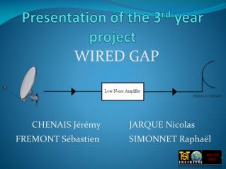
Presentation of the 3rdyearproject WIRED GAP CHENAIS Jérémy JARQUE Nicolas FREMONT Sébastien SIMONNET Raphaël
Wired Gap • Introduction • Presentation of the 3 parts • Modifications and adaptation of the module of reception • Amplifier • Retransmission • Conclusion
Introduction • Subject: realisation of a wired gap • Use: retransmission of satellites signals in non-covered areas • Low-cost project
Modifications and adaptation • Use of an existant parabola reception module: • Low cost than creating a new one • Easy to extract signals • Adaptation of this module: • Conception • Simulation
Modifications • Horizontal polarization: • Implantation of a transistor to amplify the signal • Add of electric wire to supply power • Extraction of the signal
Modifications • Vertical polarization: • Implantation of a transistor to amplify the signal • Add of electric wire to supply power • Extraction of the signal
Modifications • Output for horizontal and vertical polarization signals
Modifications • Power supply for both of transistors
Adaptation • Necessity to export the signal in 50Ω at the entry of amplifier part: • Conception • Simulation • Realisation
Adaptation - Conception • Adaptation for horizontal polarization: =>Difficulty because very disadapted
Adaptation - Conception • Adaptation for vertical polarization: • Easier than horizontal polarization • Smaller circuit than previous
- Low noise amplification - Compensation of losses in free space - very low power involved (some pW) Amplifier – Simulation part
Amplifier – Simulation part Gain Return loss
Amplifier – Simulation part Gain Return loss
Amplifier – Conception part • Conception of the mask and the circuit • Test of the transistor at IETR • Analysis of results : • comparisonwiththeory • Calculation of the number of levels • Conception of the amplifier (whenresultswereworthwhile) • Test of the amplifier
Amplifier – Conception part Circuit of the amplifier
Amplifier – Conception part • Final results , three solutions: • Retry with co-planar technology • Modify the position of components • Change of substrate : => drawback: the cost increase
Retransmission antenna • Aim : • To emit (or to broadcast) a signal in the bandwith from 10,7 to 12,7 Ghz • Solution considered first : • Simple patch antenna • Double polarization • Adopted solution : • Patch antenna network • Double polarization
Simple patch antenna • Advantages : • Simplicity of the circuit • Simplicity of adjustments • Speed of simulation • Drawback : • Isotropic antenna
Patch antenna network • Advantage : • Directed radiation diagram • Drawbacks : • Complex circuit • Very heavy simulation
Realization steps • Calibration of the antenna's characteristics (only one patch) • Installation of the network • Simulations and results
Conclusion • Low cost and important gain • Easy to use • No visual pollution
Debate Questions ?