Download
1 / 21
230 likes | 699 Views
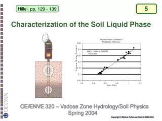
Liquid phase sintering of CIS and CIGS. Table of contents. Sintering: Basic Liquid phase sintering Liquid phase sintering of CuInSe 2 & Phase transformation of CuInSe 2 Conclusion Idea. Driving force for sintering. Reduction of excess surface energy by

E N D
Table of contents • Sintering: Basic • Liquid phase sintering • Liquid phase sintering of CuInSe2 • & • Phase transformation of CuInSe2 • Conclusion • Idea
Driving force for sintering Reduction of excess surface energy by Coarsening Densification
Sintering stages Neck growth Relative density ~ 60% Continuous pore channel around grain edges Pores pinched off at corners
Intermediate stage Most of the densification of a powder compact occurs during the intermediate stage
Factors to affect sintering kinetics Temperature ↑ Diffusion↑ DR↑ Green density ↑ Pore volume↓ Diffusion path↓ DR↑ Uniformity of green compact ↓ Non-uniform shrinkage → induces crack Atmosphere Change γSV & vapor pressure Particle size distribution Narrow → Decrease abnormal grain growth Wide → More compact density Particle size ↓ Surface↑ Driving force↑ DR↑
Liquid phase sintering Liquid phase formed between particles during sintering process Liquid phase → easy diffusion path for atoms High densification rate Two important densification mechanism Rearrangement Solution-precipitation
Rearrangement If liquid flux is well-wet on particle: Pores are formed in the liquid phase and Negative pressure is each pore: Tends to decrease in this liquid-vapor Pore surface area and over-all surface energy → Driving force leading to densification No direct contact between solid particles Seperation of 0.005-0.04 micron due to repulsive forces between particles or to an effectively rigid, tightly held liquid film Pressure results in an increase in chemical potential or activity of the solid Phase at the contact points according to the relations rp
Rearrangement 65 vol% solid particles 35 vol% solid particles Complete densification
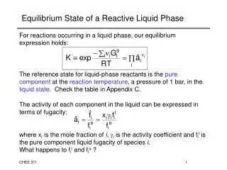
Solution-precipitation 3. Precipitation 2. Diffusion 1. Dissolution By thermodynamical relation, Solubility is increased as chemical potential increases
Liquid phase sintering of CIS and CIGS Low VOC & FF of screen-printed CIS solar cell : Poor morphology of the CuInSe2 layers Case of CdTe sintering: Sintered CdTe using CdCl2 flux VOC > 800mV is achieved In case of CIS sintering, Volatile flux materials for CIS sintering : Se, CuCl
Liquid phase sintering of CIS and CIGS Using volatile flux: Se flux: At 450℃, Only wets C+IS CIS should be In-rich to be p-type semiconductor CuCl flux: Only wets CI+S Increase in Cu/In and metal/Se ratio during sintering By exchange reaction Better composition Better morphology Better & Performance & Good morphology is important for the cell characteristics
Liquid phase sintering of CIS and CIGS Non-Volatile flux CuSe have melting point of 523℃ Cu2Se have melting point of 1113℃ Se+CuSe vs. Se+Cu2Se Only Se+Cu2Se improves the sintering → Cannot be explained with the theory of liquid phase sintering
Liquid phase sintering of CIS and CIGS Phase relation between CuSe & Cu2Se: Over 387℃, 2CuSe → Cu2Se + ½Se But with Se overpressure, CuSe phase is stable ※ Reason of selenium loss during sintering In case of In-rich CIS: Formation and evaporation of In2Se Sintering of CIS + CuxSe: Only extreme amount of CuSe improve sintering But with Se overpressure, CuSe phase is stable Sintering of CIS + CuxSe + Se: Improve sintering (In case of final composition is Cu-rich) Sintering of Cu2Se + In2Se3 Reaction to CuInSe2 is too fast to allow a sintering action of Cu2Se
Liquid phase sintering of CIS and CIGS Purdue Univ. η=3.2% Sphaleritenanocrystals (Synthesized in high temperature) Annealing in Ar, 500℃, 1hr. (Evaporating organics) Annealing in Ar/Se, 550℃, 30min. (Sintering) Sphalerite CIS can contain a large amount of excess copper Phase transform to stable chalcopyrite -> Precipitation of CuSe Melted CuSe improve sintering quality (in case of Cu-rich) Candidates for reason of Cu-rich composition Exchange reaction by residual precursor CuCl In2Se loss by insufficient Se over pressure
Conclusion • Liquid phase sintering : High densification rate • There is no appropriate liquid flux for In-rich CIS yet • Liquid phase CuSe can be formed during CIS sintering and it is useful for densification, • but it is not very helpful for formation of In-rich CIS layer • Development of liquid flux for In-rich CIS layer is required for good densification at • low-temperature
Idea Step 1. Heating over 523℃ Melting of CuSe and densification Interlayer prevents reaction between CuSe and InSe Step 2. Heating to higher temperature Melting of interlayer CuSe and InSe react to form CuInSe2 InSe-( )-CuSe particle Step 1. Heating over 523℃ Melting of CuSe and densification Shell layer on InSe particle prevents reaction between CuSe and InSe Step 2. Heating to higher temperature Melting of Shell layer CuSe and InSe react to form CuInSe2 InSe-( ) particle + CuSe particle

![[Sintering]](https://cdn2.slideserve.com/3866196/sintering-dt.jpg)