Download
1 / 23
260 likes | 555 Views
5-4: SI Fiber Modes. Consider the cylindrical coordinates. Assume propagation along z,. Wave equation results. Using separation of variables. n is integer. 5-4: SI Fiber Modes. Wave equation results. Solutions are Bessel functions. Using boundary conditions, modal equations results.

E N D
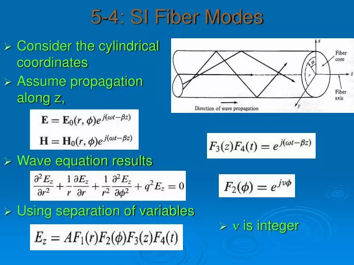
5-4: SI Fiber Modes • Consider the cylindrical coordinates • Assume propagation along z, • Wave equation results • Using separation of variables • n is integer
5-4: SI Fiber Modes • Wave equation results • Solutions are Bessel functions • Using boundary conditions, modal equations results
5-4: SI Fiber Modes • There will be m roots for each n value designated bnm • Corresponding modes are: TEnm TMnm EHnm HEnm • Fiber modes are hybrid except those for which n=0, i.e. TE0m (Ez =0),TM0m (Hz =0) • A mode is cutoff when it is no longer bound to the core • V, normalized frequency, is a parameter connected to the cutoff
Modes • Mode chart • HE11 has no cutoff unless a=0 • Linearly polarized modes • When D<<1, we can introduce weakly guiding fiber approximation • Under such approximation, similar b modes can be grouped • {HE11},{TE01, TM01, HE21},{HE31, EH11} etc.
Modes • Using: • Conclude with bjm and LPjm • Mode chart
Naming Modes • TE (TM): • E (M) perpendicular to Z, small component of M (E) in Z • Ray is meridional • TEM: • E & M are perpendicular to Z • Only mode of a single mode fiber • Helical (Skew) Modes (HE and EH) • Travel in circular paths • Components of both E and M in Z direction • Linearly Polarized Modes (LP) • Summarizes all above
Mode numbering • TE, TM, and TEM: numbers correspond to # of nulls in their energy pattern • LPjm: m is number of maxima a long a radius of a fiber, and j is half the number of maxima around the circumference
Modal Intensity distributions LP01 LP11 LP21 LP22 LP03 LP12 LP41
Number of modes • For EM radiation of wavelength l, the number of modes per unit solid angle is: • Area is the one the fiber enters or leaves, • Total number of modes: • Solid angle: • Angle: • Finally: • Approximation • Solid angle: • Valid for large V (> 10) • Number of modes • But V is:
Single Mode Propagation • Occurs when waveguide supports single mode only • Refer to modal curves, V<2.405, or a/l<2.405/2p(NA) • Actually two degenerate modes exist • Due to imperfect circular fiber, they travel at different velocities exhibiting fiber Birefringence • Small effect in conventional fibers (~10-8)
Single mode • Index profiles and modal fields • Gaussian fit
Mode field • Mode field: measure of extent of region that carries power • w/a=0.65+1.69V-3/2 +2.879V-6, for 1.2<V<2.4 • SMF: MFD ranges 10.5 – 11@ 1550 nm • This Gaussian approximation helps in calculating important parameters of SMF
Modes in GRIN • n2≤neff≤n1 • We will consider parabolic profile • Number of modes, N=V2/4 • Transverse field patterns • Single mode condition
5.6: Pulse Distortion • Pulse distortion: • SI fibers: Modal distortion: mode mixing • Power limited • BW limited • Exchange of power between modes • SI fibers • How it reduces distortion? • Modal distortion • It increases attenuation • Dispersion • Material • Waveguide • SI fibers: Modal distortion • Was found to be: D(t/L)=n1D/c • Typical for glass fibers~67 ns/km • Practical: 10-50 ns/km? • Mode mixing • Preferential attenuation • Propagation length
Pulse Distortion • SI fibers: Modal distortion: propagation length • SI fibers: Modal distortion: preferential attenuation • Higher order modes suffer greater attenuation • How it reduces distortion? • It increases total attenuation • Small length not enough to excite high order modes • SI fibers: Dispersion: Waveguide • Dl: source linewidth
Dispersion • Waveguide dispersion • Material dispersion • Total Dispersion: • D(t/L)dis=-(M+Mg) Dl • Waveguide dispersion can be neglected except for l~1.2-1.6 um • Total pulse spread, Dt • Modal distortion is dominant in MMSI fiber • Narrowing the source linewidth is ineffective, LED is used
Single Mode Fiber • No modal distortion • Material and waveguide dispersion • For short wavelength, material is dominant • Fig 5-26 (MD only) • For l~1.3 um, waveguide dispersion should be considered
Single Mode Fiber • Fig 5-27: total dispersion • -ve MD cancels +ve WD • Long high-data-rate systems can be constructed @ these wavelengths • Dispersion shifted fiber • Dispersion flattened fiber • Index profiles • Polarization mode dispersion: 2 orthogonal polarizations of HE11
Single Mode Fiber • In conventional SMF, dispersion exist at 1550 nm: Requires dispersion compensation • Dispersion compensating fiber: has opposite dispersion at higher order modes • Cutoff wavelength: • For n1=.., n2=.., a/l<3.17 for SM condition. @l=0.8 um > a=2.54 um. If l is changed to 1.3 um, same fiber still SM • @l=1.3 um > a=4.12 um, which is not SM at 0.8 • l @ which SM equation is equality is cutoff wavelength lc • l < lcwill excite MM propagation • lc=2.61 a NA
GRIN fiber • Smaller modal distortion than SI • D(t/L)=n1D2/2c • Comparing with SI, reduction of 2/D • For n1=1.48, n2=1.46, D =0.0135 >> 2/D =148 • SI typical modal is 67 ns/km, GRIN is 0.45 ns/km • MD is dominant at 0.8-0.9 um >> LD is used • At higher wavelengths, MD is small >> LED can be used
Total Pulse Distortion • Dtά L, is expected • Dtά L1/2, is found • Equilibrium length, Le • Modal pulse distortion: • Dt=LD(t/L) for L≤ Le • Dt=(L Le)1/2D(t/L) for L≥ Le • Le ά 1/mode mixing • Little mode mixing >>Le is large >> good fiber • No mode mixing >>Le is ∞>> linear dependance • Lots of mode mixing >>Le is small >> poor fiber • M&WD is independent of mode mixing >> Dtά L • Care should be taken when computing Dttot