Download
1 / 23
240 likes | 441 Views
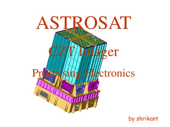
ASTROSAT. CZT Imager. Processing Electronics. by shrikant. BLOCK DIAGRAM OF AS-CZ-EL-01. Detector box AS-CZ-DT-01. 80C32 based data handling system. DUAL PORT RAM. HBT DATA TO SSR. DUAL PORT RAM. FPGA. 80C86 based data handling system. DUAL PORT RAM.

E N D
ASTROSAT CZT Imager Processing Electronics by shrikant
BLOCK DIAGRAM OF AS-CZ-EL-01 Detector box AS-CZ-DT-01 80C32 based data handling system DUAL PORT RAM HBT DATA TO SSR DUAL PORT RAM FPGA 80C86 based data handling system DUAL PORT RAM Telemetry, Telecommand & power interface
There are 3 major components in AS-CZ-EL-01 • 80C32 based system handles the detector data handling, ASIC control & detector control. • 80C86 based system handles data computation & overall CZT imager control. • FPGA based system handles telemetry & telecommand system.
Interfaces There are two basic interfaces: • Detector interface • Satellite interface
80C32 – Detector Interface 80C32 based data handling system Detector box AS-CZ-DT-01 ASIC control signals Dual 4-channel mux 80C32 Data Detector data signals Clock 0.5s intr. 2 Detector command signals Data + h/s Dual port RAM2 Dual port RAM1 To 80C86 To FPGA
80C32 – Detector Interface This interface involves: • Reading detector data every 0.5s. This is in form of 2 x 2kbytes frames per detector at 500kbps. • Analyzing & transferring detector data to 80C86 & FPGA for SSR. • Controlling detector by sending serial commands. • Sending control / configuration data to ASICs.
Detector data interface • Detector interface is a serial link consisting of clock & data. • Data will be in the form of 2kbyte frames. • Two such frames per quadrant will be downloaded by the processing unit at the rate of 500kbps. • It will take 262ms to download complete data.
Detector commands Interface • Commands to detector will be serial 16-bit data commands. This will be a single line common to all 4 quadrants. The 16-bits are as follows: Where: • Msb 2 bits denote sync bits. • N2, N1 are as follows:
Detector command interface • M4, M3, M2, M1 are as follows:
ASIC interface • This is a serial link consisting of clock & data. • There will be 4 separate lines for configuring the 4 quadrants. • Data comprises of 680 bits per ASIC. • Each quadrant has 32 ASICs • Hence for 4 quadrants there are 87040 bits. • Clock frequency will be 500kbps. That will take 175ms for configuring all the four quadrants.
Satellite Interface 80C86 based data handling system 4kx16 Dual port RAM Command Latch Handshake Command Data FPGA based telemetry handling system To SSR Serial Data Clock Latch To LBT From Telecommand
Satellite Interface This interface involves: • Power interface: Total power consumed is 2.5W. • Data formatter interface. • BMU interface: • Telemetry interface • Telecommands interface. These are divided into two: • Pulse commands. These will be of 5V & 16ms duration. • 16-bit serial data commands. This will consist of a 8khz clock, 32-bit data & 16ms duration transfer pulse.
Commands interface There are 13 pulse commands: • CPU Reset • Quadrant1 on • Quadrant1 off • Quadrant2 on • Quadrant2 off • Quadrant3 on • Quadrant3 off • Quadrant4 on • Quadrant4 off • Main power on • Main power off • Redundant power on • Redundant power off
Commands interface Data commands are subdivided into: • Executable commands: Where: • The Msbit =0 denotes executable command. • A0.. A6 is the address where the routine will branch. • N1, N2, N3 is as given below:
Commands interface • Data substitution commands: Where: • The Msbit =1 denotes data based command. • A0.. A6 is the address where nibble D3..D0 will be substituted. • M = 0 denotes D3..D0 lsnibble. = 1 denotes D3..D0 msnibble. • N1, N2, N3 is as described above.
Telemetry (BMU) interface • It comprises of 40khz serial clock, serial address, P/S, ALE signals from telemetry & serial data from processing unit. • There will be 16 channels per quadrant. These are: • VCO Data: • +5 V monitor • +10 V monitor • Veto HV monitor • Alpha voltage monitor • Temperature 1 • Temperature 2 • Temperature 3 • Temperature 4 • Counter data: • LLD and below E1 • E1 – E2 • Above E2 • Alpha trigger • Veto trigger • Software Counter 1 (< E1) • Software Counter 2 (E1-E2) • General byte Sampling rate = 16 secs • Analog channel: • +5V monitor Sampling rate = 16 secs Sampling rate = 16 secs Sampling rate = 4 secs
Data formatter interface This is parallel interface includes: • 8-bit data bus. • One active low request line. • One clock line. The request line will be polled every 20ms. When found low the data formatter will respond with a burst of 2048 clock pulses at 6.56MHz. 8-bit data will be transferred on the -ve edge of the clock.
80C32 – 80C86 Interface 80C32 based data handling system 4kx16 Dual port RAM 16-bit Buffer Commands 80C86 based data handling system
80C32 – 80C86 Interface This interface involves: • Transfer of data to 80C86 in the form of 2kbyte frames via dual port RAM. • To & fro handshaking signals to synchronize data transfer. • Commands to 80C32 via a 16-bit buffer.
Comparison table for using uc+up v/s single up • Detector data is read every 500ms. At 500kbps, it takes 65.536ms to read data of one quadrant. Hence it takes 262.144ms to read all the four quadrants. • This leaves 238ms for the following tasks: • Putting out data to SSR. • Computing the various modes of operation. • Putting out data for BMU. • Reading commands & doing likewise. • Controlling the ASICs & the DIBs via serial link.