Multispectral Imager Design
Multispectral Imager Design. for Nanosatellites. V.H.R.I. Doedee, R. Deerenberg, E.Dokter – Faculties 3mE, AE & EEMCS. 1. Introduction. Nanosatellite missions so far. Education Technology Demonstration No serious remote sensing Are nano-satellites capable for remote sensing jobs?.

Multispectral Imager Design
E N D
Presentation Transcript
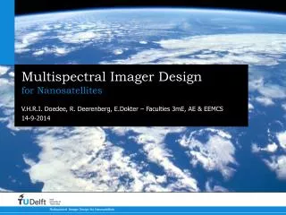
Multispectral Imager Design for Nanosatellites V.H.R.I. Doedee, R. Deerenberg, E.Dokter – Faculties 3mE, AE & EEMCS
1. Introduction
Nanosatellite missions so far • Education • Technology Demonstration • No serious remote sensing Are nano-satellites capable for remote sensing jobs?
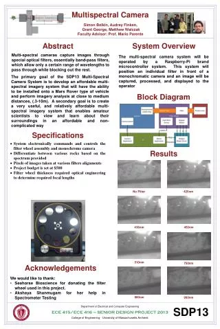
Major Constraints • volume less than 10 cm x 10 cm x 15 cm • power consumption less than 3.0 W • mass less than 1.5 kg • imaging of preferably R, G, B, NIR, MIR, TIR bands • system should survive space environment, including ‘accidental’ sun exposures • operational life time should be at least five years
How can we achieve this? • sensors with better quantum efficiencies and lower noise • deployable instead of rigid optical systems • in-orbit calibration instead of on-ground
Potential Applications When using a constellation of nanosatellites Can increase temporal resolution of remote sensing for: • Google Earth-like applications • Precision agriculture • Climate monitoring • Disaster prevention & monitoring • Military intelligence
Contents • Basics of Remote Imaging • CCD & CMOS • Orbit • Noise • Motion Compensation • Questions?
2. Basics of Remote Imaging
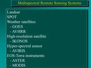
Basics of Remote Imaging Sensing in the (optical) EM Spectrum Multispectral: multiple bandwiths UV; ultraviolet, 0.1-0.4 μm VIS; the visible range, 0.4-0.7 μm NIR; the near infrared range, 0.7-1.1 μm SWIR; the short wave infrared range, 1.1-2.5 μm MWIR; the midwave infrared range, 2.5-7.5 μm LWIR; the long wave infrared range, 7.5-15 μm Source: http://www.antonine-education.co.uk/physics_gcse/Unit_1/Topic_5/em_spectrum.jpg
Resolution Spatial Spectral Radiometric Temporal
Spatial Resolution • Smallest measure of seperation between two objects that can be resolved by the system [T.A. Warner et al, 2009] • Rayleigh Criterion • Nominal Spatial Resolution Source: http://www.fas.org/man/dod-101/navy/docs/es310/EO_image/IMG00003.GIF
Spectral Resolution • Unitless Ratio: Source: http://www.cas.sc.edu/geog/rslab/rscc/mod1/specres.gif
Radiometric Resolution • How fine a difference in incident spectral radiance can be measured by the sensor [T.A. Warner, M. Duane Nellis, G.M. Foody, 2009] • Quantization of incoming radiation
Temporal Resolution • Time to refresh images
EM Propagation and Sensors • Optical sensors act like photon detectors • Energy needed (bandgap): • Band gap sets an upper limit
Materials • Silicon (Si), 0.4-1 μm • Indium Gallium Arsenide (InGaAs), 0.8-2.8 μm • Indium Antimonide (InSb), 0.3-5.5 μm • Mercury Cadmium Telluride (HgCdTe), 0.7-15 μm Wavelengths absorption of different InGaAs alloys. Source: http://www.sensorsinc.com/GaAs.html
Beam splitters • Split light waves in two consecutive beams • Cube, Plate, Pellicle • Cube and Plate: only monochromatic light, heavy • Pellicle: average transmission 50% (375–2400 nm), light, little ghosting, sensitive to vibrations Source: http://www.newport.com/store/genproduct.aspx?id=141118&lang=1033&Section=Detail
3. CCD & CMOS
CCD (Charged-coupled devices) • ‘Traditional leader’ • Great fill factor (~95%) • High Quantum efficiency
CMOS (Complementary metal-oxide-semiconductors) • Less circuitry required • Low power consumption • Individually read-out • Cheap
CCD vs CMOS CCD: CMOS: + create high-quality, low noise images - more susceptible to noise + greater light sensitivity (fill factor, QE) - lower light sensitivity • 100 times more power + consume little power • Complex + easy to manufacture • Expensive + cheap
4. Orbit
Orbit Dusk-Dawn Orbit: No eclipse – No power storage needed. Same illumination condition surface Earth. Easy data collection. Altitude = 400 Km: Typical nanosatellite perigee height. Lower altitude means better resolution. Lower altitude also means more drag. Design lifetime of 5 years achievable.
In-Orbit Calibration Normally the lens subsystem is calibrated on ground and designed such that it can withstand the launch without losing focus. This has major disadvantages • Loss of focus will always be present. • Increased risk. • More mass.
In-Orbit Calibration Why not perform the calibration in-orbit? Advantages: • Less risk. • Less mass. • Can use the same mechanism of a possible deployable lens Disadvantages: • Less precise calibration • Not a simple solution!
In-Orbit Calibration How it works: The camera makes an image, adjusts the focal length slightly and takes another image. The two images are then compared. And if the process is beneficial to the quality of the image then the process is repeated. Images are compared either on: • The satellite itself – More dedicated electronics. or • The ground – Issues with communication.
5. Noise
Signal to Noise Ratio - SNR The SNR is a measure of the quality of the taken image. There are two ways to increase the SNR: • Decrease noise as much as possible • Increase Integration time to decrease single shot noise such as Shot Noise Read out Noise etc…
Thermal Noise Thermal Noise is one of the easiest ways to decrease noise. Materials emit a certain amount of electrons according to their temperature. Decreasing the temperature of the sensor would decrease Thermal Noise significantly. (factor 2 for every 6 degrees of cooling)
Thermal Control In order to decrease Thermal Noise, the sensor must be cooled. But: Thermal control of a nanosatellite is difficult due to it’s limited size • No Active control can be applied • Only Passive control is an option: Thus the satellite must be coated with a coating with high emissivity and a low absorption factor.
Further decreasing SNR Other types of noise are dependent on the sensor and electronics. Such as: • Quantum Efficiency (QE) – Measure of efficiency of the sensor, this value should be as high as possible within the required spectrum. • Amplifying noise • 1/f noise • Etc… This should be as low as possible but this will increase the cost of the S/C.
Integration Time Some values of noise are a single event values, these do not increase with measurement time. When the time in which we view an object (Integration Time) is increased, the SNR goes up. This is however not a simple task since the S/C is moving with respect to the ground: Blurring effect.
6. Motion Compensation
Motion Compensation Two ways in doing so: • Mechanical movement of the lens subsystem to track a point on the ground. • Time Delay Integration - TDI.
Mechanical movement method. In order to view the same point on the ground a tilting mirror can be placed in front of the lens subsystem to reflect the rays of light. The motion of this mirror has to be synchronized with the movement of the S/C w.r.t the ground. • This increases complexity since moving parts are necessary • Increase in power consumption • Increase in development cost • But large integration time is achievable.
Time Delay Integration - TDI Time Delay Integration is a method which uses no moving parts. Instead it uses an array of pixels. When the satellite passes a point on the ground, the first pixel takes a measurement, and the pixel is read out. Due to the motion of the spacecraft, the same point can be seen by the next pixel in the direction of flight after a small time step. This holds for the entire pixel array. This method is also called push broom scanning
Time Delay Integration - TDI Some advantages/disadvantages: • Smaller Integration time achievable • No CCD sensor can be used, only CMOS • Much lower mass • Tested and proven method.