Download
1 / 40
400 likes | 491 Views
This director’s review highlights the personnel involved in the upgrade project, the existing XFT operations, configuration details, reasons for the upgrade, and projections for luminosity profiles, trigger configurations, and high-luminosity scenarios. Current XFT operations, hit and segment finding methods, track formation, and cable data details are discussed. The need for trigger cross section reduction and sample triggers for single tracks, leptons, and two-track scenarios are explained. The challenges and insights from the original Run 2b trigger table, including track-based triggers, trigger cross section estimations, physics unique to CDF, and the strategies to handle increasing data rates and particle interactions, are presented.

E N D
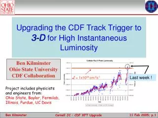
Upgrade of the CDF Track Trigger for High Luminosity Running XFT 2B; Director’s Review
Personnel on XFTIIb • Baylor University: Dittman, Krumnack • FNAL: Holm, Shaw • University of Illinois: Budd, Junk, Kasten,Levine, Mokos,Pitts, Rogers, Veramendi • Ohio State University: Hughes, Johnson,Kilminster ,Lannon, Parks,Winer • Purdue University: Jones Students Engineers Post-Docs Faculty XFT 2B; Director’s Review
eXtremely Fast Tracker = Level 1 Track Trigger CDF Trigger System • Role of tracking • Top, W/Z, ExoticPhysics triggers require High momentum electron and muon Level 1 trigger candidates • Bottom Physics require low momentum tracking at the Level 1 trigger • electrons • muons • hadronic tracks • L1 Trigger Primitives • Electrons: XFT track + EM cluster • Muons: XFT track + muon stub • L2 Trigger Tracks • XFT Track + Silicon Hits XFT 2B; Director’s Review
Outline of Current XFT Operation • Hit Finding: Mezzanine Card • Hits are classified as prompt or delayed (i.e. “2-bin”) • Segment Finding • In the axial layers, search for patterns of prompt/delayed hits consistent with High Pt tracks • Each segment found is assigned a pixel (phi, all layers) and possibly a slope (outer 2 axial layers only) • Track Finding • Looking across 3 or 4 axial layers, search for patterns of segments consistent with Pt>1.5 GeV/c • Resultant Pt and Phi of all 1.5 GeV/c tracks sent on to XTRP • Maximum of 288 tracks reported Good hit patterns are identified as segment, then segments are linked as tracks XFT 2B; Director’s Review
Current XFT Configuration Ansley trigger cable (220 ft) Data @45MHz LVDS ~2 m copper Cable Data @33MHz (channel link) Neighboring cards connected over backplane 168 TDC from COT axial layers 24+24 Axial Finders 24 LOMs 24 Linkers ~10 m of cable to XTRP XTC 3 crates 24 crates 3 crates XFT 2B; Director’s Review
Why an Upgrade? • The XFT was designed for a luminosity of: • L=1x1032cm-2s-1 396nsec bunch • <int/crossing> ~ 3 • L=2x1032cm-2s-1 132nsec bunch • <int/crossing> ~ 2 • Accelerator Performance • Max luminosity attained: 1x1032cm-2s-1 • Expect maximum of L=3x1032cm-2s-1 at 396nsec bunch crossing • <int/crossing> ~ 9 • Factor of 3-4 above design XFT 2B; Director’s Review
Luminosity Profile • Approximate “design” projections for Lpeak • Spring 2005 Phase 2 8.5E31 (slip stacking) • ACHIEVED SUMMER 2004! • 1.1E32 as of July 16, 2004! • Fall 2005 Phase 3 1.25E32 (recycler/e–cool) • Spring 2006 Phase 4 2.25E32 (stacktail) • Spring 2007 Phase 5 2.75E32 (run) • These are the numbers that get 8.5 fb–1 • “base” projection for maximum Lpeak is 1.57E32 • This is the number that gets 4.4 fb–1 XFT 2B; Director’s Review
Extrapolating to Higher L • Assume we can ultimately achieve L1A / L2A / L3A = 30kHz / 1kHz / 100Hz • Trigger cross sections to fit within this budget: • We currently run at 300mb / 6mb / 1250nb @6E31 • Even with constant cross sections, we can’t continue as we run now…let alone growth terms. • We need a factor of 3 reduction in trigger cross section • True “physics” cross sections are small: need to reduce Fakes! XFT 2B; Director’s Review
Sample XFT Triggers: Single Tracks and Leptons 7 GeV single track • Quadratic growth? • s(L=5E31)/s(L =0)=2.6 CEM8_PT8 • s(L =5E31)/s(L =0)=1.1 • Track cross section growing, but controlled by matching to EM cluster XFT 2B; Director’s Review
Two-Track Triggers • “Scenario C” • 2 tracks pT>2.5 GeV • Opposite charge • pT(1)+ pT(2)>6.5 GeV • df < 135 • Quadratic growth (overlaps + fakes) • s(L=5E31)/s(L =0)=1.5 • Extrapolate: • linear s(L=1.5E32) = 225mb 34kHz • Real (from overlapped MB) s(L=1.5E32) = 500mb 75kHz • This is a higher purity B trigger…prefer to run scenario A (higher rate, higher yield) but cross section 3x larger. 160mb 100mb XFT 2B; Director’s Review
Comments on Original Run 2b Trigger Table Track based triggers are a significant fraction at L1/L2/L3: L1: ~40% L2/L3: ~55% Trigger cross sections optimistic and/or unknown. Linear extrapolations! L2 high ET electron projects to ~220nb (listed at 170nb) 2 high pT b-jet unknown(1 hi pT b-jet extrapolates700nb) No track-only triggers included! Bs mixing is physics unique to CDF. We now know it takes several fb–1 of data to observe mixing. Bh+h– is physics unique to CDF. Bs is physics unique to CDF. All of these analyses are statistics limited forever. Are we really going to give up when Linst reaches 1E32cm–2s–1? We saturate the available bandwidth now. We will continue to do so for the duration of the CDF experiment. Since we will always accumulate data at the maximum possible rates, we have two handles: Improve the system to allow higher rates. Improve the purity (S/N) of the triggers. XFT 2B; Director’s Review
XFT Requirements • Physics goals • Maintain core high pT program up to L=3E32cm–2s–1 • Maintain scenario C two-track trigger to L=1.5E32cm–2s–1 • This goal is a challenge for both L1 and L2. • This balances physics goals with realistic operating conditions. • It is unreasonable to attempt to keep the current physics table beyond 1E32 cm–2s–1 • parts of the program will be modified or removed. • XFT requirements • Maintain good efficiency (>90%) for high pT tracks. • Improve purity to reduce growth terms • Maintain (or improve) pT and f0 resolution • Need a factor of ~3 reduction in extrapolated cross section XFT 2B; Director’s Review
How Should We Upgrade the XFT? • In Run IIb TDR, we advocated: • Full replacement of entire track trigger: Hit Finder, Segment Finder, Track Finder • More precise timing to obtain better segments • More segment info used to obtain better tracks • Addition of Finders for a Single Stereo Layer • Used as a veto at Level 1 • Very aggressive schedule • Requires downtime while we bring the new system up • An alternate strategy • Keep current axial system as is • Add Finders on 3 outer Stereo Layers • More precise timing to obtain better segments (“6 bin”) • Used as a Veto at Level 1 • Used in extrapolation and matching for leptons at Level 2 • No downtime required: axial system is not modified • System will be commissioned in parallel “Baseline” “Rescope” XFT 2B; Director’s Review
“Rescoping” The XFT Upgrade Luminosity extrapolations uncertain for RunIIb TDR Only had data up to L=0.3x1032cm-2s-1 Software Model of COT Uncertain Used Monte Carlo “mixing” of events Observed performance degradation of the COT Concern that baseline was not good enough with compromised COT Needed to develop tools to study this Manpower limited Present situation Now have luminosity up to ~1.0x1032cm-2s-1 Can now mix COT data events to simulate higher luminosity much more accurately Performance of COT has recovered (and is expected to stay that way!) Added personnel 4 post-docs in the past year 3 engineers 3 institutions Went from 3 people to 20! XFT 2B; Director’s Review
XFT Simulation and High Luminosity • All events are passed through a hit-level simulation • Start with COT hits • Gives exactly the same answer as hardware when run with same masks, roads and XFT hits • Outputs XFT hits, pixels, and tracks for axial and XFT pixels for stereo • Association of stereo pixels to axial tracks done after simulation • Simulate High luminosity by Merging events “main” event with zero bias • Merge COT hits (combine overlapping hits) • Add track collections from individual events together • Don’t re-run tracking avoids problems with offline tracking at high luminosities • Offline tracks serve as “truth” for the event • This method allows us to probe up to 4E32 • Test Merging by comparing merged events with real data events XFT 2B; Director’s Review
Validation Using Recent Data (XFT Pixels) • Average number of XFT pixels (segments) versus luminosity • Less sensitive to issues of dead wires masked on, etc. XFT 2B; Director’s Review
Validation Using Recent Data (Tracks) • Average number of XFT versus luminosity • Event merging is an excellent tool for predicting high luminosity performance • Outstanding agreement between merged data and actual data • This tool was not available at the time of the Run IIb TDR XFT 2B; Director’s Review
Stereo Simulation Implementation SL7 SL6 SL5 Expected pixel position (z = 0) Measured pixel position (z 0) pixel (SL7) Displacement from stereo angle SL5 has opposite displacement from SL7 pixel (SL5) Upgrade adds 3 stereo layers (~doubling info) Current XFT uses 4 axial layers only Stereo algorithm exploits correlation expected for real tracks XFT 2B; Director’s Review
Impact on A Specific Trigger • Scenario C Two-Track Trigger XFT 2B; Director’s Review
Evaluating The Rescoped Upgrade Evaluating The Rescoped Upgrade XFT 2B; Director’s Review
XFT Upgrade Configuration Ansley trigger cable (220 ft) Data @45MHz LVDS ~2 m copper Cable Data @33MHz (channel link) Neighboring cards connected over backplane 168 TDC from COT axial layers 24+24 Axial Finders 24 SLAMs 24 Linkers ~10 m of cable to XTRP 2 bin XTC 3 crates 24 crates 3 crates New cable (~150ft) Optical Data ~45MHz ~3m optical Cable @60.6MHz New TDC or 6-bin XTC for stereo layers 12+12+12 Stereo Finders 2 crates Data to L2 XFT 2B; Director’s Review
Main Components of the Upgrade • New Hit Finders for Stereo Layers • Functionality provided by new (Chicago) TDC *or* • New XTC card to be used on current (Michigan) TDCs • Important change: go from 2 bins (prompt/delayed) to 6 bins • New Stereo Finder Boards • Require new transmission method of data from TDC to St. Finders • Require new Finder chips • Method to Use Stereo Information at Level 1 • New Boards: Stereo Linker Association Module (SLAM) • SLAMs replace the current Linker Output Modules • Method to Use Stereo Information at Level 2 • Use Existing Pulsar System: no new electronics needed • Firmware development required to implement algorithm used in simulation studies XFT 2B; Director’s Review
Stereo TDC Mezzanine Board • Illinois developing 6 time-bin TDC mezzanine board. • Prototypes assembled. • Have configured FPGAs and CPLDs via JTAG • Urbana test stand operational, working on data capture tests XFT 2B; Director’s Review
Data Flow: TDC to Finder Boards • Built a fiber test board to evaluate fiber optics for the XFT upgrade. • Have perform successful send/receive loop tests • taking significant advantage of fiber optic R&D done for CMS by the Fermilab group XFT 2B; Director’s Review
Stereo Finder Board Layout Stereo Finder board schematic started Schematic of mezzanine card done; layout started XFT 2B; Director’s Review
The Axial Finder Chip Pixel Output Mask finding 140 inputs Dead COT wire list L1 and L2 storage Axial Finder: implemented using Altera FLEX 10K70 chip. Stereo Finder: targeting Altera Stratix EP1S25 chip XFT 2B; Director’s Review
6 Bin Finder Chip Firmware Progress Currrently have written and compiled onto simulated Stratix chips the mask finding firmware for all 9 of the 6-bin Finder chip designs (3 misses * 3 Stereo SLs ) • Can compare compilation analysis of this design and 2-bin design on various chips 2-Bin, Flex 10K, complete design • 130 / 189 pins (68%) • 6,912 / 36,864 memory bits (18%) • 3,347 / 3,744 Logic Elements (89%) • Actual time : 23 MHz (43.00 ns) 2-Bin, Flex 10K, Just mask finding • 72 / 189 pins (38%) • 0 / 36,864 memory bits (0%) • 2,041 / 3,744 Logic Elements (55%) • Actual time: 45 MHz (22.4 ns) 6-Bin, Stratix 1S25, just mask finding • 151 / 707 pins (21%) • 0 / 1,944,576 memory bits (0%) • 13,002 / 25,660 Logic Elements (50%) • Actual time : 150 MHz (6.6 ns) Expect remaining infrastructure in chip to increase total LE’s to ~19,000, well under the 25,660 LE’s available XFT 2B; Director’s Review
How does design scale to 6 Bins? Time Demultiplexer L1 Pipeline Mask Finding Input wire buffer LE: 29 (*3) LE: 504 (*3) LE: 241 (*3) LE: 2090 (*7) Mem: 0 Mem: 0 Mem: 6912 (*3) Mem: 0 in: 72 (*2) in: 130 (*3/2) in: 26 (*3) in: 26 (*3) • Simplification of finder chip schematic showing resource use of major components • Expected increases shown when going to 6 Time bins LE : logic elements Mem: memory In: inputs to block Scales up Stays same Total LEs : 2-bin : 3,000 6-bin : 19,000 Conservatively on high side, … XFT 2B; Director’s Review
SLAM Board Layout Stereo at Level 1: SLAM Board • SLAM Board replace Linker Output Module • Transmits Track list in each 15o-slice to extrapolation electronics • Receives stereo Finder segments and associates with axial tracks • Schematic done; layout begun SL3 Optical Links VME Interface SL5 Optical Links SLAM Chip XTRP Cable Linker Input (via backplane) SL7 Optical Links XFT 2B; Director’s Review
Using Stereo at Level 2 CDF Trigger System • 6-bin improvement over 2-bin mask resolutions • s(curv): ~3-3.5x smaller • s(): 2.5x smaller • Rejectiononly improve • L2 has time to send more info • 3-D track variables: • z0, Mtt, • SVT: Barrel-track match • Extrapolation for lepton triggers • Implementation • Use existing hardware (PULSAR) • Requires development of firmware for stereo algorithm XFT 2B; Director’s Review
½ of L2 system Hotlink or TLK1501 36 Stereo Finders 4 Pulsars FPGA FPGA FPGA FPGA FPGA FPGA • 4 pulsars • 3 Finders + 1 for neighbor pixels • 90+30 /pulsar • 45+15 / FPGA • Pulsars already have complete XFT axial tracklist and L1 trigger bits built in • 1 additional Pulsar • Concatenation • Send to L2 processor Pass through version of firmware done. XFT 2B; Director’s Review
Schedule (Broad View-I) • Stereo Finder Card: (FNAL) Boards: 36 + spares • Preproduction Design—Assembly : 6/04 – 12/04 • Preproduction Testing: 12/04 – 3/05 • Production (Checkout) : 1/05 – 7/05 (10 Wks) • TDC Trans Card: (Ill) Boards: 126 + spares • Preproduction Design – Assembly: 6/04 – 11/04 • Preproduction Testing: 11/04 – 2/05 • Production (Checkout): 2/5 – 6/05 (10 wks) • SLAM Board (OSU) Boards: 24 + spares • Preproduction Design – Assembly: 7/04 – 11/04 • Preproduction Testing: 11/04 – 2/05 • Production (Checkout): 2/05 – 7/05 (8 Wks) Joint Tests: 12/05 – 1/05 Joint Tests: 12/05 – 1/05 XFT 2B; Director’s Review
Schedule (Broad View-II) • Stereo XTC Card: (Ill) Boards: 126 + spares • Preproduction Design—Assembly : Done • Preproduction Testing: 6/04 – 8/04 • Production (Checkout) : 9/04 – 3/05 (10 Wks) • L2 Stereo Interface: (Ill/FNAL) • Fabrication/Assembly: 7/04 – 11/04 • Testing: 12/05 – 2/05 • TDC to Finder Fibers (FNAL/CDF) Fibers: 324 • Purchase: 7/04 – 9/04 • Installation: 9/04 – 10/04 • Other Fibers: • Finder to SLAM (216 Fibers) and Finder to Level 2 (36 Fibers) • Spec & Purchase: 9/04 – 11/04 Joint Tests with Stereo Finder Boards: 1/05 – 2/05 XFT 2B; Director’s Review
XFTIIb Tasks • Baylor University: Dittman, Krumnack • Fiber specification • New XTC, testing, commissoining • FNAL: Holm, Shaw • Stereo Finder board, Finder chip • University of Illinois: Budd, Junk, Kasten,Levine, Mokos,Pitts, Rogers, Veramendi • New XTC, COT transition card, L2 Stereo • Simulation, testing software • Ohio State University: Hughes, Johnson,Kilminster ,Lannon, Parks,Winer • SLAM board • Simulation, commissioning • Purdue University: Jones • Finder testing, checkout, commissioning XFT 2B; Director’s Review
XFT Upgrade Cost Breakdown NOTE: Costs do not include overhead or contributed university engineering XFT 2B; Director’s Review
Conclusions • Accelerator performance has been excellent • Records seemingly weekly….great! • But…high luminosity at 396nsec bunch spacing leads to many interactions/crossing • We need to upgrade the XFT to take advantage of the great oppurtunity • The RunIIb XFT Upgrade will meet the needs of high luminosity running • This upgrade gives us the required factor of 3 rejection of fakes • System can be installed and commissioned with no impact on the current XFT • Not all capabilities have been explored • Current studies only used 2 of 3 stereo layers • Expect another factor of ~2 by using stereo extrapolation in Level 2 • Mass triggers are also possible at Level 1/2 XFT 2B; Director’s Review