Download
1 / 22
220 likes | 396 Views
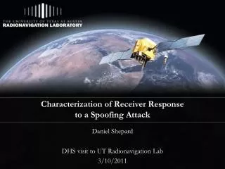
Characterization of Receiver Response to a Spoofing Attack. Daniel Shepard and Todd Humphreys Presentation at ION 2011| September 22, 2011. Overview. Anatomy of a Spoofing Attack Questions to answer Test Procedure Test Results Summary of Findings. Anatomy of a Civil GPS Spoofing Attack.

E N D
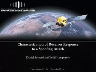
Characterization of Receiver Response to a Spoofing Attack Daniel Shepard and Todd Humphreys Presentation at ION 2011| September 22, 2011
Overview • Anatomy of a Spoofing Attack • Questions to answer • Test Procedure • Test Results • Summary of Findings
Anatomy of a Civil GPS Spoofing Attack • A spoofer seeks to alter a target receiver’s Position-Velocity-Time (PVT) solution by transmitting fictitious GPS signals • Attacks considered Proximity Spoofing Attacks which were first envisioned by Logan Scott in 2003 • A typical spoofing attack involves: 1) alignment, 2) increase power, 3) carry receiver off
GPS Dependency Begets Vulnerability Telecommunications Network Smart Grid: Synchrophasor Measurement Units (SMUs)
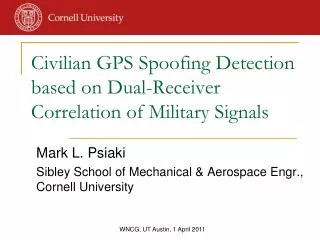
Zhang Paper on Synchrophasor Spoofing • Considers the effects of a Spoofing Attack or Time Stamp Attack on fault location using SMUs • However, these results failed to consider any limits on spoofer induced dynamics
Research Questions to Assess Critical Infrastructure Vulnerability • Would a jamming-power-to-noise-power (J/N) type jamming detector trigger on a spoofing attack? • How aggressively can receiver dynamics be manipulated by a spoofing attack?
Would a J/N-type jamming detector trigger on a spoofing attack? • Power ratio (η): Ratio of spoofing signal power to authentic signal power • A power ratio above 3 would cause input power to exceed 95% of natural variation J/N-type jamming detector would trigger • What power ratio is required for reliable spoofing? Pspoof Pauth
How Aggressively can Receivers be Manipulated? • We would like to know: • How quickly could a timing or position bias be introduced? • What kinds of oscillations could a spoofer cause in a receiver’s position and timing? • How different are receiver responses to spoofing? • Approach: Determine maximum velocity at which a receiver can be spoofed over a range of accelerations without: • Causing loss of lock of satellites • Raising alarms v a t
How Aggressively can Receivers be Manipulated? (cont.) • These are some potential shapes for the velocity-acceleration curves • Green: represents the region where a spoofer can operate without being detected • Red represents the region where a spoofer might be unsuccessful
Tested Receivers • Science receiver: CASES receiver • Developed for Ionosphere monitoring • Telecommunications Network Time Reference Receiver: HP 58503B • Commonly used in cell phone base stations (Symmetricom predecessor) • High quality Ovenized Crystal Oscillator (OCXO) steered by the GPS time solution
Tested Receivers (cont.) • Power Grid Time Reference Receiver: SEL-2401 • Provides timing for power grid Synchrophasor Measurement Units (SMUs) • Low quality Temperature Controlled Oscillator (TCXO) slaved to the GPS time solution • Name brand receiver: Trimble Juno SB
The Civil GPS Spoofer • Introduced in 2008 by Humphreys • Improved Spoofer capable of: • Tracking all L1C/A & L1C signals • Producing up to 10 L1C/A spoofed signals • Precise code phase alignment and frequency lock • Data bit prediction • Remote control of spoofer suggested position, velocity, and acceleration and signal power via internet
Test Setup RFSA • A National Instruments Radio Frequency Signal Generator (RFSG) produced 6 GPS signals at constant power • The spoofed signals were summed with the RFSG signals • This combination was fed to: • the target receiver • a National Instruments Radio Frequency Signal Analyzer (RFSA) used for visualization RFSG Signal Conditioning Control / Feedback Computer Target Receiver Spoofer
Procedure • Power Ratio • Spoofed Velocity and Acceleration 1. Power Adv. = x dB 2. Attempt Carry-off 3. Check for Success (Remove Authentic Signal) 4. Measure the Power 1 m/s 1. Acceleration = a m/s2 2. Velocity = v m/s 3. Check for Success (watch for alarms) 4. Iterate until a maximum velocity is found vmax found? v no a yes t
Results: Power Ratio • A power ratio of about 1.1 or greater is needed to capture a target receiver with high confidence • This increase in absolute received power is well below the natural variations due to solar activity • Implications: • A spoofing attack would easily evade detection by a J/N sensor: J/N sensors are necessary, but not sufficient • Downstream signal processing is crucial for reliable spoofing detection
Results: Spoofed Velocity and Acceleration • The data points collected for each receiver were fit to an exponential curve of the form: • This curve fit: • Defines the upper bound in the velocity-acceleration plane below whicha sophisticated spoofer can successfully spoof that particular receiver • Can be used to assess the security implications of a spoofing attack
Results: Spoofed Velocity and Acceleration of Science Receiver • Notice the asymptote at 5 m/s2 acceleration • Maximum speed is only limited by the dopplerfrequency range to around 1300 m/s (4.3 μs/s) • Implications: • Acceleration limited to 2 m/s2 due to phase trauma • No limitation on velocity up until the receiver is unable to track the signal
Results: Spoofed Velocity and Acceleration for Telecommunications Network Time Reference Receiver • Due to this receiver placing trust in the frequency stability of its oscillator, it cannot be moved very quickly • Maximum achievable speed in time is 2 m/s (6.67 ns/s) • Implications: • Can still be carried 10 μs off in time in around 35 min, which would disrupt call hand-off
Results:Spoofed Velocity and Acceleration for Power Grid Time Reference Receiver • Can be easily manipulated by the spoofer • Corresponding induced phase angle rate is shown for a 60 Hz phasor • Implications • Can reach a maximum speed of 400 m/s resulting in a phase angle rate of 1.73o/min • Oscillations are not possible due to the low acceleration capability of spoofer
Results:Spoofed Velocity and Acceleration for Name Brand Receiver • Most easily manipulated receiver tested to date • Can be accelerated continuously at about 25 m/s2 until the dopplerfrequency range is reach at a velocity of about 1300 m/s • Implications • Large accelerations and velocities may be possible in many name brand receivers
Trimble Resolution SMT • Suggested to be unspoofable based on tests performed at White Sands Myth Busted Quite Spoofable
Summary of Findings • We’ve never met a civil receiver we couldn’t spoof • J/N-type jamming detector won’t catch a spoofer, but does restrict it • There are vast differences in the dynamic response to spoofing between receivers • Large oscillations in position and timing are difficult to induce due to low acceleration capability of the spoofer • Areas of vulnerability exist in CDMA cell phone networks and the power grid