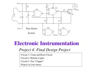
Project 4: Final Design Project
Circuit 1: Count and Reset Circuit Circuit 2: Holiday Lights Circuit 3: The “Clapper” Project of your choice. Trip Alarm System. Project 4: Final Design Project. The Final Design Project. Should combine concepts that you have learned in this class

Project 4: Final Design Project
E N D
Presentation Transcript
Circuit 1: Count and Reset Circuit Circuit 2: Holiday Lights Circuit 3: The “Clapper” Project of your choice Trip Alarm System Project 4: Final Design Project
The Final Design Project • Should combine concepts that you have learned in this class • Ideally should involve some digital electronics, but does not have to. • You have three projects to choose from, or you can find one of your own. Electronic Instrumentation
Circuit 1: Count and Reset Circuit • Counts to a binary number and then resets itself back to zero. • This one will count to 4. You need to design one that counts to 10. Electronic Instrumentation
Use a 555-Timer Circuit for the Clock • Pulses must be slow enough to be counted • Place LED’s at the outputs of the counter to show it is counting. Electronic Instrumentation
1 Logic 0 1 0 • The logic uses the output of the counter to send a high signal to the reset pin when it reaches count+1 • This resets the counter back to zero and it counts again. 101 resets counter 1 Electronic Instrumentation
Circuit 2: Holiday Lights • Must create your own logic to make at least three distinct light patterns. Electronic Instrumentation
Use a 555-Timer Circuit for the Clock • Pulse frequency should make display look like its intended purpose – holiday lights Electronic Instrumentation
Logic • The counter already puts out 4 distinct signals • You must, however, add at least one additional gate. • Try to use the gates in your kit or check with us to see which gates are available before you get carried away. Electronic Instrumentation
Circuit 3: The Clapper • This circuit uses a microphone to detect two sharp sound waves or “claps”. • When the claps are detected, it switches a relay that can be connected to an electric device. Electronic Instrumentation
Note familiar components • Microphone, 741 op amp, 555 timer, flip flop, relay, transistor as switch, and 9 volt battery. Electronic Instrumentation
Circuit Operation • A single hand clap will be picked up by the electric microphone which is coupled through C1 into the op amp. • The output triggers the 555 timer which is configured as a monostable multivibrater. • The trigger pulse is stretched by the 555 and outputs a pulse to a D type flip flop. • Because of the three state counter arrangement of the flip flop, two sharp claps are required before it will output a high to the transistor. • The transistor turns on the relay and any device connected to K1's switch contacts. • Two more claps will clock the timer again and will turn it off. Electronic Instrumentation
Power problem requires circuit redesign • Components circled in yellow must be powered by 5 volts and the microphone by 2.5 volts and not 9 volts. • You must make these changes. Electronic Instrumentation
Circuit of your choice • Find a schematic and build the circuit. • Buy a kit and put it together. • (The above circuit is a trip alarm system found on the web.) Electronic Instrumentation
Find a schematic and build the circuit. • Many schematics that do interesting things are available free on the web. For example: • Alarm circuits • Frequency doublers and dividers • Rain detector • Battery charger • Audio amplifiers • Motion detectors • Sites with schematics: • http://commlinx.com.au/schematics.htm • http://www.techlib.com/electronics/index.html • http://www.uoguelph.ca/~antoon/circ/circuits.htm Electronic Instrumentation
Schematic stipulations • Try to choose a schematic that you can understand and uses components • in your kit • available in the studio • that you are willing to buy • You must get your schematic approved by the instructor for your section. Electronic Instrumentation
Buy a kit and put it together. • Many pre-packaged kits are available for sale. Many are inexpensive. For example: • Cliff hanger game ($11) • Battery tester kit ($9) • Coin toss kit ($4) • Rover robot kit ($16) • Solar lightening bug kit ($13) • Lie detector kit ($5) • Sites with kits: • http://www.chaneyelectronics.com/ • http://www.kitsusa.us/store/ • http://www.electronickits.com/kit/complete/complete.htm Electronic Instrumentation
Kit stipulations • Try to choose a kit that you can understand and uses components that we have studied. • You must get your kit approved by the instructor for your section. • If your kit requires soldering, we have solder and soldering irons in the studio. We will set them up on the center table. Electronic Instrumentation
Project Report • You will not be required to do a major write-up for this project. • You will be required to hand in the following: • Signed output from the circuit or a signature from the staff attesting that the circuit was working. • A description of how the circuit works • What are the blocks? • What does each block do? • Extra Credit Available: see write-up for details Electronic Instrumentation
Practical Questions • You should be able to describe the function of your circuit • You should be able to divide your circuit into blocks. • You should be able to connect your circuit to the power supply and to the ‘scope, if necessary. • You should be able to capture the scope signal both as a picture and data, using Agilent Intuilink software • You should be able to design your logic using Pspice. • You should be able to create a truth table of your logic and demonstrate it works as expected. • You should be able to describe the function of individual gates or circuit blocks. Electronic Instrumentation