Download
1 / 36
360 likes | 457 Views
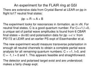
FLAIR meeting , GSI March 15-16 2004 Positron Ring for Antihydrogen Production A.Sidorin for LEPTA collaboration JINR, Dubna. Contents 1. Antihydrogen in-flight 2. LEPTA – the positron storage ring with electron cooling of positrons and particle “magnetization”

E N D
FLAIR meeting, GSI March 15-16 2004 Positron Ring for Antihydrogen Production A.Sidorin for LEPTA collaboration JINR, Dubna
Contents 1. Antihydrogen in-flight 2. LEPTA – the positron storage ring with electron cooling of positrons and particle “magnetization” 3. Scheme of the Antihydrogen Generator based on the LEPTA type ring 4. Possible experiments with antihydrogen in-flight 4.1. Direct comparison of the electric charges of proton, antiproton, electron and positron 4.2. Hyperfine structure of the ground state 4.3. Spectroscopy of excited states, Lamb shift measurement 4.4. Laser spectroscopy of 1S – 2S transition 5. Status of the LEPTA project 6. Conclusion
1. Antihydrogen in-flight Basic idea: G.Budker, A.Skrinsky,Uspekhi Fyz. Nauk, 124 (1978) 561
The facility general scheme p~ e Electron cooling of antiprotons Antiproton ring H~ e Electron cooling of positrons e+ Positron ring
Antihydrogen flux quality Angular and velocity spread is determined by the antiproton beam parameters - deep cooling of antiprotons “Magnetised” cooling - in absence of additional heating the equilibrium is determined by temperature of longitudinal degree of freedom of the electrons Antiproton beam ordering - ? Stability of the string coherent oscillations At 20 keV maximum antiproton number is about 105
Antihidrogen flux intensity Generation rate per 1 antiproton: To increase the positron beam density: - positron deceleration in the recombination section, - positron beam compression - bunched positron and antiproton beams
Magnetic field in recombination (cooling) section 1. Positron (electron) beam transport 2. Suppression of IBS in positron (electron) beam - preservation of flattened distribution 3. “Magnetised” cooling B1 ~ 100 G B2, B3 ~ 1 kG
Magnetic field in recombination (cooling) section Antiproton motion distortion Larmor radius of antiprotons has to be less than recombination section: at 5 MeV and Lrec = 3 m B < 1 kG at 50 keV B < 100 G At small antiproton energy and large magnetic field one needs to adjust the recombination section with antiproton ring
Scheme of The Electron Cooler at Large B: Beams Injection / Extraction
Magnetic field in positron source 1. Positron source based on Electron linac: low magnetic field 2. Positron source based on Radioactive isotope: large magnetic field
W - foils Ta - convertor Electron beam Positron flux Low energy positron source based on Electron linac
Electron energy is ~ 200 MeV Intensityis about 108 positrons per pulse Magnetic field < 100 G
Positron source based on radioactive isotope Prototype is the positron part of ATHENA Positron source and moderation The efficiency of this type moderator lies in the range from 0.2 to 0.5%. The positron energy spread at the exit of moderator is about 2 - 5 eV. The flux intensity at the exit is about 1-2106 slow positrons per second
Positron trapping Magnetic field ~ 1 kG Trapping efficiency is 60% Number of trapped positrons is about 108 Repetition period ~ 100 sec
Two basic concepts 1. 200 MeV Electron linac for positron production ~ 50 G magnetic field in the positron ring Positron ring circumference of 10 - 15 m Positron energy of about 1 keV Positron deceleration to ~ 10 eV in the recombination section 2. Positron production using radioactive isotope ~ 500 G magnetic field in the positron ring Positron energy of about 10 keV Positron beam compression and deceleration in the recombination section Matching of the antiproton beam with recombination section “LEPTA - type” ring
2. LEPTA – the positron storage ring with electron cooling of positrons and particle “magnetization” I.Meshkov, A.Skrinsky, NIM A379 (1996) 41 ; NIM A391 (1997) 205 I.Meshkov, A.Sidorin, NIM A391 (1997) 216
Low Energy Positron Toroidal Accumulator Septum e+ trap Collector e-gun e+ source Quadrupole Cooling section Detector B
General parameters of the LEPTA Circumference, m 17.8 Positron energy, keV 10.0 Solenoid magnetic field, G 400 Quad field gradient, G/cm 10.0 Positron beam radius, cm 0.5 Number of positrons 1108 Residual gas pressure, Тоrr 110 Electron cooling system Cooling section length, m 4.0 Beam current, A 0.5 Beam radius, cm 1.0 Electron density, cm-3 1.6108 Orthopositronium flux parameters Intensity, atom/sec 110 Angular spread, mrad 1 Velocity spread 1104 Flux diameter at the ring exit, cm 1.1 Decay length, m 8.5
3. Scheme of the Antihydrogen Generator based on the LEPTA type ring
Scheme of The LEPTA Type Positron Ring 5800 6900
#2 Facility parameters and H-bar generation Positron ring Ring circumference, m 25 Recombination section length, m 3 Positron energy in the ring, keV 10 Positron beam radius in the ring, cm 0.5 Magnetic field in the positron ring, G 400 Magnetic field in the recombination section, G 1000 Positron number 108 Antiproton ring Energy, MeV 50 5 0.1 0.02 Circumference, m 52 52 36 36 Antiproton number “normal” state 1010 107 106 106 ordered state 3.4106 1.6106 3.9105 3105 Positron energy in the recombination section, keV 26 2.6 0.054 0.01
#2 Facility parameters and H-bar generation (continuation) Antihydrogen flux parameters Energy, MeV 50 5 0.1 0.02 Generation rate per 1 antiproton 110-8 2.510-8 810-8 110-7 Flux intensity, s-1 “normal” state 100 0.25 0.08 0.1 ordered state 0.034 0.04 0.03 0.03 Angular spread “normal” state 10-4 ordered state< 10-6 Relative velocity spread “normal” state10-4 ordered state 10-6
4. Possible experiments with antihydrogen in-flight I.Meshkov, Phys. Part. Nucl. 28 (1997) 496
4.1. Direct comparison of the electric charges of proton, antiproton, electron and positron - – Test of CPT Theorem The experiment concept : Detection of a displacement x of "neutral" atoms, when they travel in a transverse magnetic field Bof the length L: x = (e·BL2) / (2pc) ,
#4.1 Charge inequality |q1+ q2| / e Particles 1, 2 Theory Experiment PresentExpected Proton / electron 0 ? <121 - Antiproton / positron 0 ?<25 (indirect) 29 Proton / antiproton < 2· 10-18 <25 29 Electron / positron < 2· 10-18 <4 410
#4.1 The experiment concept CsI “Atoms” B CsI CsI Positionsensitive detector “The atoms” : H0 H-bar o-Ps Required parameters Magnetic field, T 10.0 10.0 2.0 Magnet length, m 10.0 10.0 10.0 Detector resolution, mcm 2.0 2.0 100.0
#4.1 One of the goals of the LEPTA project is the experiment EPOCC (Electron/Positron Charge Comparison) - direct comparison of the electric charges of proton, antiproton, electron and positron to exceed the present accuracy of the charge difference by two orders of magnitude : |qp+ qe| / e < 410-8 => 410-10 .
4.2. Hyperfine structure of the ground state An achievable resolution ( / )HFS < 3·10 – 8 Antiproton magnetic moment from ( / )HFS : Absolute value: a / a < 2·10 – 5 (presently3·10 – 3) Difference with proton: | p + a | < 1·10 – 7 The method: Atomic interferometer with sextupole magnets.
4.3. Spectroscopy of excited states, Lamb shift measurement Hydrogen : Hyperfine structure 2S-state / ~ 310–7 Lamb shift of 2P-state / ~ 210-6
#4.3 Microwave spectrometry of 22S1/2 22PJ transitions (J = 1/2, 3/2) Detector H-bars 22S1/2 12S1/2 ERF RF Cavity tuned to transition 22S1/2 1/7 s 22 P1/2 1.52 ns 12S1//2
4.4. Laser spectroscopy of 12S1/2 – 22S1/2 transition The goal of ATHENA and ATRAP experiments at CERN : / < 110-12 Life time of the metastable 22S1/2 state ~ 1/7 s , i.e. ( / )natural ~ 10-17 . Experiment in traps with Hydrogen today ( / )transition ~ 10-12 What about H-bars in-flight ?
#4.4 Doppler free two photon spectroscopy of 12S1/2 22S1/2transition (principle scheme) RF cavity 12S1/2and22S1/2 Mirrors Detector H-bar 12S1/2 22S1/2 12S1/2 ftransition = 1. 233·1015 Hz transition = 0.12 Laser = 0.24 Laser frequensy in the particle Rest Frame (PRF): PRF=Laser·· (1 ) , Two photon energy is H-bar velocity dependent : = 2 ћ - scan by vH-bar ! 22S1/2 1/7 s 22P1/2 12S1/2 Laser beam
#4.4 Doppler free spectroscopy of 12S1/2 22S1/2transition Experiment parameters: Antiproton energy, MeV 50 5.0 = v/c 0.31 0.1 H-bar flux, s-1 “normal” state 100 0.25 ordered state 0.034 0.04 Relative velocity spread v / v : “normal” state10-4 ordered state 10-6 22S1/2 1/7 s 22P1/2 12S1/2 Experiment resolution / ~ 0.1 of Doppler spread: / ~ 0.122 (v / v) “normal” state10-6 10 -7 ordered state 10-8 10-9
October 2003: 3/4 of the ring is assembeled and traced with pulsed electron beam
6. Conclusion For technical design of the positron ring one needs: Experimental study of the particle dynamics in a ring with longitudinal magnetic field Experimental study of electron cooling of positrons Choice of the installation concept providing best conditions for experiments