Download
1 / 25
250 likes | 272 Views
This presentation discusses the design, realization, and low power RF tests of the C-Band structure prototype for the SPARC energy upgrade. It includes details on the design of single-cell and coupler, as well as the results of high power RF tests at KEK.

E N D
Advancements on RF systems D. Alesini (LNF-INFN) Quinto Meeting Generale Collaborazione LI2FE, Frascati 15-16/03/2011
OUTLINE • C BAND STRUCTURES FOR SPARC ENERGY UPGRADE • (D. Alesini, et al., DESIGN, REALIZATION AND LOW POWER RF TESTS OF THE C BAND STRUCTURE PROTOTYPE FOR SPARC, SPARC-RF-11/002, 1 February 2011) • Design: single cell, coupler • Realization: prototype • Results of high power RF test at KEK • 2) NEW S-band RF Gun • Design: 2D profile, coupler Realization • 3) Time schedule
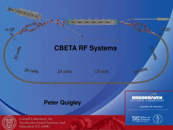
SPARC ENERGY UPGRADE ACC. SECTION GUN The SPARC energy will be upgraded from 170 to >240 MeV by replacing a low gradient S-band traveling wave section with two C-band units. We decided to implement this system at SPARC to explore the C Band acceleration (RF components, construction at LNF TW sections, SLED, syncronization) in hybrid scheme with S Band: -Higher gradients -Very promising from the beam dynamics point of view Klystron N°1 3 dB splitter ATT E ≈ 170 MeV 20 ÷ 22 MV/m ≈ 130 MeV ACC. SECTION ACC. SECTION PULSE COMPRESSOR ≈ 13 MV/m Klystron N°2 C-band acc. structures > 35 MV/m • The new C-band system consists mainly of: • 2 accelerating sections (1.4 m long) • 1 C-band klystron (50 MW), by Toshiba Ltd (JP) • 1 Pulsed HV modulator supplied by ScandiNova (S) • WR187 waveguide system • 400 W solid state driver supplied by MitecTelecom (CDN) • SLED E > 240 MeV 1.4 m 1.4 m ≈ 50 MW ≈ 50 MW C-band Station 2.5 μs ≈ 100 MW/0.20μs 5712 MHz – 50 MW C-band ENERGY COMPRESSOR
THE C BAND STRUCTURE AND PROTOTYPE Previous the construction of the two TW sections, a prototype with a reduced number of cells, has been realized. The goals of this prototype were: -test all design and construction procedure -test the structure at high power at KEK (Japan) in the framework of a collaboration between LNF-KEK. The design activity has been divided in three different parts Splitter: to have a symmetric feeding system. Coupler design: based on the “new generation” of couplers proposed at SLAC for high gradient X Band structures (waveguide couplers) Single cell design: optimized to work with a SLED RF pulse
SINGLE CELL DESIGN The structure has been designed as TW constant impedance (cells with equal radius) in order to: -simplify the fabrication -reduce the peaksurface field when the structure is feed by a SLED pulse -reduce the unbalance between the accelerating field at the entrance and at the end of the structure, due to the combination of power dissipation along the structure and SLED pulse profile. Elliptical shape The single cell has been designed: -exploring the different TW cell parameters as a functiion of the iris aperture (a), thickness (t) and ellipticity (r1/r2). -combining the parameters with the real RF SLED pulse and calculating the maximum surface field, accelerating field,....
SINGLE CELL OPTIMIZATION The dimensions of the single cell have been optimized to simultaneously obtain: -lowest peak surface electric field on the irises with the SLED input pulse; -an average accelerating field of, at least, 35 MV/m with the available power from the klystron; -the largest iris aperture for better pumping, reduced wakefields contribution and reduced filling time of the structure (related to the breakdown rate probability). Safety value (V. Dolgashev) at least in X Band Reduction of the Attenuation Reduction of the magnetic field (pulsed heating) Elliptical shape
COUPLER DESIGN The design of the coupler has been divided in two parts: -the design of the waveguide coupler; -the design of the splitter. splitter waveguide coupler Advantages: -integrated symmetric feeding -low H field pulsed heating -Better pumping Disadvantage: -multipolar field components (quadrupole)
COUPLER DESIGN: QUADRUPOPLE COMPONENT ANALYSIS The coupler is a compact transition between a rectangular geometry (the waveguide) and a circular one (the cavity). It introduces, in the waveguide region, multipolar field components. Due to the symmetric feeding of the system this components have an even periodicity with respect to the azimuthal angle. Integrated quadrupole gradient in the first and second coupler (Keq) as a function of the injection phase. In the same figure it is plotted the energy gain.
STRUCTURE REALIZATION V. Lollo
REALIZATION OF CELL AND COUPLERS @ COMEB Cooling pipes Cells Turning machine “Shaumblain” Cell Ra<0.05m tolerances 2m Tuning by deformation Input coupler cumputer controlled milling machine Ra<0.2m tolerances 10m Output coupler: Electro discharge machining Ra<1.2m tolerances 20m R. Di Raddo, V. Lollo
BRAZING @ LNF • The structure has been brazed @ LNF in several steps: • -Cells • Couplers • Final brazing • Intermediate RF measurements have been done during realization Main problem during the realization: -alignment of coupler and cells in the final brazing process
LOW POWER RF MEASUREMENTS THE STRUCTURE WAS NOT YET TUNED S11=0.078 (expected 0.005) S13=0.648 (expected 0.647) S12=0.641 (expected 0.647) Exciting from the load Exciting from the input coupler
HIGH POWER TESTS AT KEK: OVERVIEW 1.5 months of high power RF test have been done @ KEK Control room C Band Klystron X Band test room C Band test room
HIGH POWER TESTS AT KEK: TEST AREA (1/2) SLED Prototype
HIGH POWER TESTS AT KEK: TEST AREA (2/2) loads prototype Ionic pumps
STRUCTURE CHARACTERIZATION AT HIGH POWER PF=klystron output power
S-BAND GUN: main modifications vs present gun Construction of a NEW gun with some modifications from the electromagnetic and vacuum point of view with respect to the present SPARC gun: 2D DESIGN -elliptical iris profile -larger iris diameter -larger beam pipe aperture 3D DESIGN -tuners removal -rounded coupler slot -larger coupler slot -Reduction of the surface electric field -Better pumping -Bigger -/3 modes separation (short RF pulses) -Reduction of the surface pulsed heating -Better pumping -Higher coupling coefficient (=2) (short RF pulses)
2D: Elliptical shape of the iris and larger iris diameter According to previous considerations on gun profiles (L. Faillace et al., SPARX-RF-07/001, 2007) -The iris diameter (2riris) has been increased up to 36 mm (in the current gun it is 25 mm). This allows shifting the /3 mode of more than 40 MHz and also allows pumping better the half cell. -it has been adopted an elliptical shape of the iris with a ratio 2 between the axes (b/a). This allows reducing the surface peak electric field on the iris. -the iris thickness (2a) has been maintained to 20 mm (in the current gun it is 22 mm) -the beam pipe diameters has been increases from 25 mm (current) up to 36 mm a b riris rpipe
2D: Final dimensions and parameters In the present gun the maximum peak electric field on the irises is 1-1.07 times the field on the cathode. With the elliptical shape it decreases to about 0.85-0.9 times the field on the cathode 20 mm 3 mm 4.5 mm 36.74 mm 53.04 mm 18 mm 16 mm
3D: coupling coefficient choice tpulse=1s; Pin@=1=20 MW; Pin@=2=16 MW; Final choice: =2
3D: coupler design Machining compatibility HFSS model Rounded coupler for pulsed heating reduction: T=60oC @ 120 MV/m; 2s (Present gun>150oC) Hot spot The strongly rounded coupler introduces multipolar field components (a factor two bigger than in the present gun).
GUN REALIZATION • Our proposal is to realize the gun without brazing but with RF/vacuum gaskets. The advantages are: • Hard copper (not brazed) that gives BDR much lower than copper treated with brazing • The gun is much more easy to realize (backup solution: in case of problems the gun can be brazed) gaskets Electron beam welding A. Battisti, V. Lollo
TEST OF COPPER GASKETS prototype -3 different gaskets/RF contacts have been tested to simulate the waveguide, the cells and the vacuum pump port. The gaskets have been successfully tested at different temperature (up to 250 C) with different thermal cycles. We are confident that this technical solution can be adopted
Time schedule C Band sections GUN