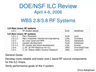
Main Linac RF Systems Program: Performance and Cost Optimization for ILC-like RF Sources
Demonstrate RF system performance for TDR, finalize design approaches, build industrial versions, measure reliability, understand cost and mass production path, identify potential vendors. Use an ILC-like RF source in a 'string test' to power an RF unit. Program overview for FY08-09 includes funding and target goals. Develop modulators, klystrons, charging supplies, modulator evaluation, and more. Testing conducted at FNAL, DESY, KEK, and SLAC to evaluate and optimize RF systems. Plans to select best designs and build units for testing and production.

Main Linac RF Systems Program: Performance and Cost Optimization for ILC-like RF Sources
E N D
Presentation Transcript
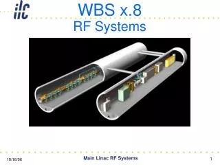
WBS x.8RF Systems Main Linac RF Systems
FY08-09 Overarching Goals • Demonstrate rf system performance at the level required for the TDR • Design approaches finalized • Industrial versions built • Reliability measured at few 10 khr level • Cost and path to mass production understood • Potential vendors identified. • Use an ILC-like rf source in a ‘string test’ to power an rf unit (3 cryomodules). Main Linac RF Systems
FY08-09 Program Overview • FY08 • Target 1 = 10 M$ • Target 2 = 12 M$ • FY09 • Target 1 = 12 M$ • Target 2 = 17 M$ Main Linac RF Systems
Target 1 and Target 2 Target 2 Target 1 Main Linac RF Systems
Target 2 Funding Program • 2 DFM Marx (started in FY07) • 6 Modulator Production Units • 2 Second Generation 10 MW MBKs (started in FY07) • Sheet Beam Klystron (started in FY07) • 6 Klystron Production Units • 4+4 RF Distributions Systems to FNAL (1½ in FY07) • 32+32 Processed Couplers to FNAL (12 in FY07) • Coupler Development at FNAL and SLAC • 1 Production RF Source to FNAL and 5 at SLAC • RF system for new CM Test Stand in FY09 Main Linac RF Systems
Target 1 Funding Program • 2 DFM Marx (started in FY07) • 4 Modulator Production Units • 2 Second Generation 10 MW MBKs (started in FY07) • Sheet Beam Klystron (started in FY07) • 4 Klystron Production Units • 1+2 RF Distributions Systems to FNAL (1½ in FY07) • 8+16 Processed Couplers to FNAL (12 in FY07) • Coupler Development at FNAL and SLAC • 1 Production RF Source to FNAL and 3 at SLAC Main Linac RF Systems
Modulators • Goal: Down select ILC modulator design by FY07-Q3 and have industry build six units: five for long term test at ESA and one for use at FNAL in FY09 for ILCTA. • Candidates • Baseline designs at DESY (PPT, ABB, FUG, Poynting), KEK (Nichicon) and FNAL(FNAL,SLAC) • SLAC Marx Generator • First Prototype in early FY07 • Build two DFM versions by early FY08 • DTI Direct Switch Modulator • Expect delivery to SLAC in early CY07 • DTI Marx Generator • SBIR funded – expect sometime in CY08 (not factored into program) Main Linac RF Systems
Modulators (cont) • Infrastructure/Testing • RF Test Stands at FNAL, DESY and KEK • Generally run at less than max power for cryomodule operation. • SLAC ESB • Two new dedicated test stands in FY07 capable of 24/7 operation • Evaluate Marx and DTI modulators in FY07 • Test two DFM Marx versions in FY08 (if Marx selected). • SLAC ESA • Run five new test stands 24/7 in FY09 with industry built modulators • FNAL ILCTA-NML • Run three cryomodules with industry built modulator in FY09 Main Linac RF Systems
Modulator WBS • 3.8.1.1 - Charging Supply: Build prototype and upgrade to power up to six modulators at SLAC (Common 8kV SCR + Individual 4kV Switching Supply design). Supply single-unit switching supply to FNAL in FY09 for 3-cryomodule test. • For Target 1 scope, build 3 charging supplies for SLAC, 1 for FNAL. • 3.8.1.2 – Interlock/Monitoring System: Develop HA interlock and monitoring system based on experience with two new stations in FY07. Build six of them, one of which will need to interface with FNAL controls system • For Target 1 scope, build only 4 systems. Main Linac RF Systems
Modulator WBS (cont) • 3.8.1.3 – DFM Marx: Complete fabrication of two Marx DFM units and test at SLAC ESB (half of cost in FY07). DTI modulator or original Marx to be sent to FNAL for 5 MW TH2104C klystron in NML injector. • 3.8.1.4 – Production Modulators: Based on performance/cost of Marx and DTI modulators at SLAC and Pulse Transformer modulators at DESY, KEK and FNAL, purchase three unit each from two vendors. Five to be installed in ESA and one shipped to FNAL. • For Target 1 scope, build 4 production units (3 at ESA, 1 for FNAL) • 3.8.1.5 – Modulator Evaluation: Participation by modulator experts at FNAL in performance and cost evaluation of the various modulator designs at DESY, FNAL, SLAC and KEK. Main Linac RF Systems
Klystrons • Goal: Down select klystron design by end of FY08 and have industry build six units: five for long term test at ESA and one for use at FNAL in FY09 for ILCTA-NML • Candidates • Baseline 10 MW MBK • DESY • Thales: 4 vertical tubes tested (none robust) and 4 in pipeline • CPI: 1 vertical tube tested at DESY – low efficiency • Toshiba: 1 vertical tube test at DESY – OK with > 200 hrs operation • Request for bids by DESY for ~ 3 horizontal tubes • SLAC • Buy 2nd generation vertical tubes from Toshiba and CPI in FY07 • SLAC 10 MW Sheet Beam Klystron • Design well along – build two generations of tubes in FY07-08 Main Linac RF Systems
Klystrons (cont) • Infrastructure/Testing • RF Test Stands at FNAL, DESY and KEK • Generally run at less than max power for cryomodule operation. • SLAC ESB • Two new dedicated test stands in FY07 capable of 24/7 operation • Evaluate Toshiba & CPI MBKs and SLAC SBKs in FY07/08 • SLAC ESA • Run five new test stands 24/7 starting in FY09 with industry built klystrons. • FNAL ILCTA-NML • Run three cryomodules with industry built klystron in late FY09 Main Linac RF Systems
Klystron WBS • 3.8.2.1 – MBK – Evaluate two 10 MW klystrons purchased in FY07 from Toshiba and CPI in the two test stands in ESB (started in FY07). Includes cost for solenoid power supplies, moving fixtures and supports. • 3.8.2.2 – SBK – Complete first full power prototype sheet-beam klystron (beam stick completed and full power prototype started in FY07). At ESB, test beam stick before CPI klystron and full prototype after finish Toshiba klystron. • 3.8.2.3 – Production Klystrons: Based on performance/cost of vertical MBKs at SLAC, horizontal MBKs DESY and the SBK at SLAC, purchase three unit each from two vendors. Five will be installed in ESA and one shipped to FNAL. • For Target 1 scope, build 4 production units: 3 for SLAC, 1 for FNAL Main Linac RF Systems
RF Distribution • Goal: Develop low cost, efficient and agile distribution system and have three, 8-cavity systems in operation at FNAL in FY09 • Changes being considered to baseline • Add adjustable tap-offs to maximize cavity gradients • Feed cavities in pairs via 3 dB hybrids to eliminate circulators • Use simpler phase shifters in place of three stub tuners • Use WR770 in place of WR650 for long waveguide runs • Weld Al waveguide in-situ instead of using flanges • Testing • Evolve design and provide FNAL one per year in FY07, 08 and 09. • First two will have optional circulators to allow beam operation with nl spacing of the cavities in the cryomodules. Main Linac RF Systems
RF Distribution WBS • 3.8.3.1 – Component R&D – Continue studies to lower cost of components and develop techniques for mass production (e.g. welding instead of flanges). • 3.8.3.2 – Distribution Systems for FNAL – In FY08, complete second 8-cavity system started in FY07 for TTF3 cryomodule, together with 3 more, and in FY09, build 4 ILC prototype 8-cavity systems for Type-4 cryomodule. These systems, like the first one in FY07, would be assembled and tested at SLAC and then shipped to FNAL to be installed at NML and at CM test facility. Main Linac RF Systems
Couplers • Goals: • Understand processing limitations and evaluate surface contamination • Clean, bake, assemble and rf process coupler pairs for FNAL cavities • Revaluate TTF3 and other designs to reduce manufacturing cost • Program (collaboration of SLAC/LLNL/FNAL with Orsay/KEK input ) • FY07 • RF process coupler parts • Build class 10 clean room in B006 and do surface contamination studies • Assemble and rf process 12 CPI couplers bought by FNAL • FY08-09 • Supply up to 32 couplers per year for FNAL cavities • Revaluate coupler dimensional tolerances and assembly techniques and produce low cost versions at SLAC. Explore alternative designs at FNAL. Main Linac RF Systems
Coupler WBS • 3.8.3.1 – Coupler R&D – Modify TTF3 design to lower cost and improve performance based on SLAC R&D in FY07, and on continuing R&D at Orsay and KEK. Build two prototypes each in FY08 and FY09. • For Target 1 scope, this program would be descoped. • 3.8.3.2 – Coupler Design – Explore alternate coupler designs using rf modeling programs. • 3.8.3.3 – Supply 32 TTF3 couplers in FY08 and 32 in FY09 to FNAL. SLAC would purchase couplers, assemble and rf process at ESB using the facilities developed in FY07. • For Target 1 scope, only 8 couplers would be produced in FY08, and 16 in 09, which with those from DESY and those produced at SLAC in FY07, would allow three cryomodules to be operated at NML by the end of FY09. Main Linac RF Systems
RF Sources/Unit Test • At SLAC-ESA, do long-term reliability testing of five production rf sources. • At FNAL-NML, power three cryomodules with rf system having • High efficiency, high power factor charging supply • 120 kV, 130 A, 1.6 ms, 5 Hz modulator • 10 MW, 65% efficient klystron • Low loss rf distribution system with adjustable tap-offs • High power couplers with adjustable Qext • Control system with interface to HA LLRF system and modulator/klystron interlocks. • ILC-like cooling system for klystron and racks • Operate accelerator with ILC-like bunch trains for few thousand hours. Main Linac RF Systems
RF Source Test WBS • 3.8.5.1 – Operation and Evaluation – Starting in FY09, install and operate five production klystrons and modulators in ESA (high power rf terminated in ferrite loads). Record data on performance to characterize reliability. Run 24/7 into FY10 to integrate at least 30,000 hours in total at full power and repetition rate. • For Target 1 scope, labor effort is reduced. • 5.8.1.1 – ESB Test Stand Maintenance - Maintain three L-band test stands in ESB for component, modulator and klystron testing. • 5.8.1.2 – ESA Test Stand Facilities - Install facilities in ESA in support of six test stands (only five would be used). Includes water, power, charging supply cable distribution, containment tanks, fire suppression and safety systems. • For Target 1 scope, 4 test stands would be implemented (only 3 would be used). Main Linac RF Systems
RF Source Test WBS (cont) • 5.8.1.3 – ESA Test Stand Controls - High level controls for the ESA test stands. • For Target 1 scope, this effort would be reduced. • 5.8.1.4 – ESA Test Stand Maintenance – Starting in FY09, maintain five L-band test stands in ESA for modulator and klystron testing. • For Target 1 scope, the effort would be reduced to maintain 3 test stands. • 5.8.1.5 – Send Klystron/Mod to NML - In FY09 send production modulator, klystron and waveguide to connect to existing rf distribution systems at cryomodules for rf-unit test. Send SLAC experts as needed. Main Linac RF Systems
RF Source Test WBS (cont) • 5.8.1.6 – NML RF Station Install/Operate/Maintain – Starting in FY09, install, operate and maintain SLAC-supplied L-band station at FNAL-NML. Integrate interlock system with FNAL control system. Main Linac RF Systems
RF System Integration • Goal: Complete TDR engineering design of the rf system integrated with the other systems in the beam and service tunnels • Interface with CF&S Group to finalize • Electrical connections and line loading specifications • Cooling connections and water flow and temperature stability requirements • Rack and RF component layouts • Interface with the Installation Group to • Design equipment and procedures to install components • Develop installation schedule and component check out scheme • Interface with Controls Group to • Provide high level interface to interlock and LLRF system Main Linac RF Systems
Accelerator Design • 2.8.1 – Accelerator Design – covered in WBS x.7 • 2.8.2 - Accelerator Components • 2.8.2.1 and 2.8.2.1 - RF Design at SLAC and FNAL: Write specs and work with other technical systems (civil, cryomodule, installation, controls) to create an integrated design for the TDR. • For Target 1 scope, this effort would be reduced. Main Linac RF Systems