Download
1 / 15
160 likes | 433 Views
BROOKHAVEN SCIENCE ASSOCIATES. RF systems for NSLS-II. J. Rose, A. Blednykh, P. Mortazavi and Nathan Towne. X-RAY Ring RF requirements. Bucket for 3.3MV. NSLS-II RF POWER REQUIREMENTS. Cavity Choice. High beam currents achieved by B-factories made

E N D
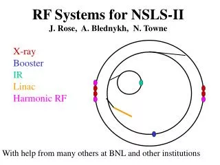
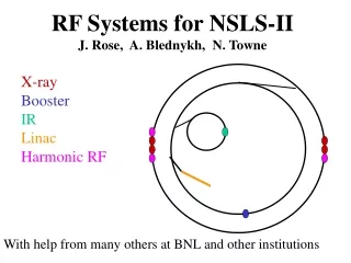
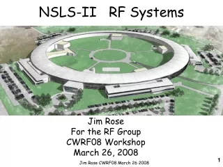
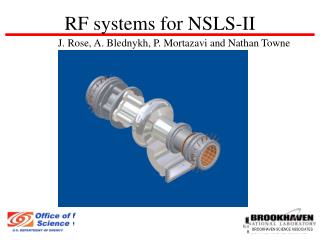
BROOKHAVEN SCIENCE ASSOCIATES RF systems for NSLS-II J. Rose, A. Blednykh, P. Mortazavi and Nathan Towne
X-RAY Ring RF requirements Bucket for 3.3MV
Cavity Choice • High beam currents achieved by B-factories made • CESR-B, KEK-B and PEP-II cavities attractive • Complex SUPERFISH analysis of CESR-B of • HOM impedances used in preliminary CBI growth • rate estimates with ZAP: maximum growth time • of 65ms for 4 cavities, less than the damping time • of 8ms • GdfidL analysis of full 3-D cavity extends analysis • to dipole modes and 3-D effects (fluted beampipe)
Cavity Modeling with CFish, GdfidL GdfidL vs. CFISH Benchmark ferrite losses, superconductor surface resistance GdfidL vs. measurements on ferrite loaded pillbox confirm GdfidL model Full Cavity HOM results used to analyze CB instability up to ~2GHz, No problems yet but need to extend to beampipe cutoff frequency of 7GHz Alexei Blednykh
Beam energy gain/cav >2.4 MV Eacc >8 MV/m Unloaded Q >7108 Frequency 500 MHz Standby (static) losses <30 W Dynamic + static losses <120W Operating Temperature 4.5 K Max. beam power/cavity <250 kW CESR-B Cavity chosen for Baseline SCRF chosen for lower R/Q, highly damped HOM’s, lower operating cost and comparable capital cost Well established commercial production. Units 15 and 16 now being produced by ACCEL. In operations at Cornell (4), CLS(2), Taiwan (2). Being commissioned at Diamond (3)
KEK-B Cavity Parameters Manufactured by Mitsubishi for KEK at 508 MHz They have produced one cavity at 500MHz *KEK has recently demonstrated 400kW per coupler KEK cavity is an option for NSLS-II *Shinji Mitsunobu SRF2005 ThP52 High Power Test of Input Couplers and HOM dampers for KEKB Superconducting Cavity
Passive Third Harmonic Landau Cavity A harmonic bunch-lengthening cavity is required to increase Touschek lifetime. Increases beam stability by increasing energy-dependent tune spread ~1/3 of 500MHz voltage, ~1 MV, can be met with one Super3HC cavity Elletra/SLS Super 3HC cryo-module
1500MHz “Super-3HC” cavity Voltage/cell 0.5 MV Eacc >5MV/m Unloaded Q >7108 Static losses <50W Dynamic + static losses <100W Operating T. 4.5 K Frequency 1500 MHz Harmonic Cavity for Bunch Lengthening Work continues on effect of bunch train transients on bunch lengthening (N. Towne) 4.9MV @500MHz required for 3% Momentum acceptance: 1.6MV @ 1500MHz requires 3 cavities N. Towne
NSLS-II RF Straight layout Two 500 MHz cavities + one 1500 MHz passive harmonic cavity fit in one 8m straight: meets initial power requirements Second straight reserved for third , fourth 500 MHz and second 1500MHz cavities as additional user insertion devices increase RF power requirement Klystrons located in adjacent RF building to minimize loop delays in feedback systems
RF Power Sources for Ring System Klystron can be sourced by multiple vendors
Low Level RF System Effect of RF jitter on the beam: Amplitude modulation of the RF fields leads to momentum deviations of the beam, Likewise phase modulations translate into amplitude modulations again leading to momentum deviations. The momentum errors affect beam size and orbit jitter as follows: The beam size in the center of the 5 m straight is given by Since the dispersion is near zero (~1mm) and the natural energy spread is <0.001 the second term is negligible and the beam size becomes σx,y= 40μm, 2.4 μm Orbit jitter is given as σx = σδ∙ηx , σy = σδ∙ηy σx′ = σδ∙ηx′ , σy′ = σδ∙ηy′ This work is in progress, and preliminary tolerances of +/- 0.5% amplitude and 0.5 degree phase have been adopted. These values have been achieved at other 3rd generation light sources.
Modeling: Future work • NSLS-II bunch length of • 4.5mm excites modes up to • elliptical beam-pipe cutoff frequency • C48 Ferrite loss factor decreasing rapidly ε′ Courtesy M. deJong, CLS μ′′ Losses declining μ′ ε′′ By combining different ferrite tiles broad range of frequencies can be damped V. Shemelin Impedance limit for 8ms damping time, 4.5mm bunch length 0 40
Booster RingRequirements Full energy booster in same tunnel 780m circumference Energy loss /turn =493 keV Vacc = 1MeV for 1% RF acceptance 7nC/macropulse, 1 per min. Beam current = ~3mA Beam power 3kW Delta-E/E Phase in 500 MHz (radians) 1 “Petra” type cavity and (1) 50-80 kW IOT
Conclusions RF systems for third generation light sources are mature technology; RF cavities and power sources available from industry The short bunch length of 4.5mm in NSLS-II means operating the CESR-B cavities in a new regime, C-48 ferrite may not meet requirements at higher frequencies: This is being studied further, new ferrite combinations appear to be direct substitutes and can be incorporated in the preliminary design phase. Work continues to define RF tolerances, however modern digital RF control systems can achieve an order of magnitude improvement over existing (APS, ESRF) systems mitigating any concerns