Download
1 / 17
170 likes | 187 Views
Explore the development and performance of a modulated OEIC-WC with monitoring capabilities, addressing challenges and future directions in high-speed communication networks.

E N D
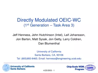
Directly Modulated OEIC-WC(1st Generation – Task Area 3) Jeff Henness, John Hutchinson (Intel), Leif Johansson, Jon Barton, Matt Sysak, Jon Getty, Larry Coldren, Dan Blumenthal University of California Santa Barbara, CA, 93106 Tel: (805)893-8465; Email: henness@engineering.ucsb.edu 4/25/2003 - 1
Overview • Objective/Scope • Demonstrate a modulated OEIC-WC with monitoring capability • Approach • Photodiode directly connected to SGDBR gain • Major Accomplishment • Designed and fabricated 1st run of 1st gen OEIC-WC • Begun initial testing/characterization • Main Issues/Problems/Limitations • Contacts, parasitics in test setup limit RF performance • Improve monitor design • Improve preamp-SOA design, SGDBR tuning, power output • Extinction ratio and chirp 4/25/2003 - 2
OEIC Approach • In-situ signal monitoring provided • No carrier lifetime limitations • Reduce pattern dependence • Increase linearity • Increase bandwidth • No filter to remove input wavelength • Separate optimization of detection and modulation • Net signal gain and programmable 2R regeneration possible • High integration density – no branching waveguides required 4/25/2003 - 3
Direct vs External Modulation Directly Modulated SGDBR Integrated External Modulator PostAmp SOA Front Mirror Gain Phase Back Mirror EAM Front Mirror Gain Phase Back Mirror Preamplifier SOA Photodetector Preamplifier SOA Photodetector 4/25/2003 - 4
PD Bias Signal Monitor 50Ω 2 1 PD Pre Amp SOA Input 3 Laser Bias SOA Bias SOA Bias 6 SGDBR Post Amp Output 4 5 Concept for Direct Mod Device Layout 4/25/2003 - 5
SGDBR Direct Modulation • Small signal bandwidth = 8GHz • 10dB extinction demonstrated at 5GHz with no mode hops 4/25/2003 - 6
Laser Efficiency Enhancements • Gain-lever • Cascaded Multiple Active Region (MAR) 4/25/2003 - 7
Directly Modulated WC Design Gain-Lever w/ Meander Post-Amp SOA Front Mirror Gain Section Phase Back Mirror Absorber Output Input (optional) Input Pre-Amp SOA PhotoDetector Signal Interconnect PhotoDetector Pre-Amp SOA • 500m PreAmp SOA into 50m active photodetector • Metal trace to carry photocurrent (data signal) to drive gain section • Meander line to provide AC block • SGDBR with 300m PostAmp SOA • Gain-lever designs included in mask (for discrete component testing) 4/25/2003 - 8
Gain Lever CW Spectra and PD Response • Gain Lever SGDBR exhibits low current turn-on • PD exhibits linear I-L response • Photocurrent enough to provide significant modulation 4/25/2003 - 9
OEIC-WC CW Conversion Spectra • in = 1540nm, out = 1546nm • Pin of 4dB gives Pout of 17dB – high differential gain 4/25/2003 - 10
Contacts – Error in Fabrication Run Issue: Large number of open circuit N-metal contacts Cause: Nitride not removed under metal – processing error Solution: Oxygen FIB to open area to underlying metal Effect: High resistivity & capacitance ground contact P-metal: Ti/Pt/Au SiN InP FIB 8kV Oxygen opening (80mx80m) N-metal: Ni/AuGe/Ni/Au Long term solution: Change mask and process flow 4/25/2003 - 11
Frequency Response • 3dB down at >2.5GHz • Clean waveform at 2.5GHz 3dB 2.5GHz 4/25/2003 - 12
Signal Monitoring • Signal via bias-tee to 50Ω scope input • 310A/mW monitor signal • -15.6dB conversion fiber-to-fiber 4/25/2003 - 13
I /N o + + H , He Implantation NV o SI InP substrate Segmented Ridge Laser(Cascaded Multiple Active Region) • N series connected diodes in one laser cavity • Differential efficiency multiplied by N • Signal/noise multiplied by N • Threshold current divided by N • Stages isolated by ion implants • Compatible with SGDBR technology Initially Funded via RFLICS 4/25/2003 - 14
CW Results for MAR Facets: uncoated Stage Temp: 20ºC Internal Loss: 12.2 cm-1 Internal Efficiency: 69.4% Heatsink: soldered to AlN Initially Funded via RFLICS 4/25/2003 - 15
Segmented Laser Performance • Linearity improved by segmentation • 3-stage SFDR = 120.3 dB/Hz2/3 • Control SFDR = 114.5 dB/Hz2/3 • High speed operation possible • 5 GHz small-signal bandwidth • Resonance-limited Initially Funded via RFLICS 4/25/2003 - 16
Current Status and Future Directions • Devices to mounted on carrier, RF probing improved • High speed measurements possible • Possibly satisfy Phase I milestones • Second mask spin will address several aspects • Improved monitor/bias connection • Improved SOA/detector design • Improved SGDBR design • Inclusion of multiple-active region embodiment • Investigation of saturable absorbers for improved extinction in digital applications 4/25/2003 - 17