Download
1 / 38
380 likes | 492 Views
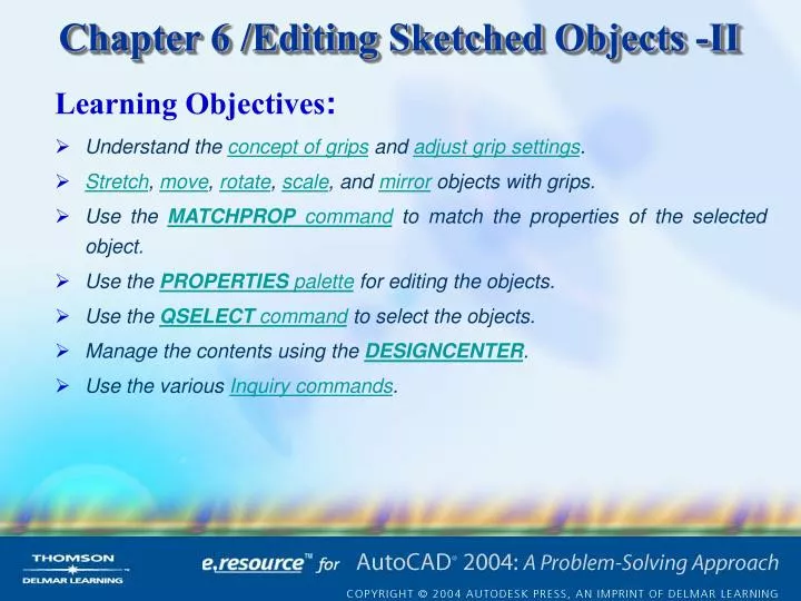
Learning Objectives :. Understand the concept of grips and adjust grip settings . Stretch , move , rotate , scale , and mirror objects with grips. Use the MATCHPROP command to match the properties of the selected object. Use the PROPERTIES palette for editing the objects.

E N D
Learning Objectives: • Understand the concept of grips and adjust grip settings. • Stretch, move, rotate, scale, and mirror objects with grips. • Use the MATCHPROP command to match the properties of the selected object. • Use the PROPERTIES palette for editing the objects. • Use the QSELECT command to select the objects. • Manage the contents using the DESIGNCENTER. • Use the various Inquiry commands.
TYPES OF GRIPS Grips can be classified into three types: unselected grips, hover grips, and selected grips. Selected grips are also called hot grips. When you select an object, the grips are displayed at the definition points of the object, and the object is highlighted by displaying it as a dashed line. These grips are called unselected grips (blue). Now, if you move the cursor over the unselected grip, and pause for a second, the grid is displayed in green color. These grips are called hover grips. Next, if you select a grip on this object, the grip becomes a hot grip (filled red square), figure. Figure showing the selected and unselected grips Learning Objectives
ADJUSTING GRIP SETTINGS The grip settings can be adjusted using the options under the Selection tab of the Options dialog box. This dialog box can also be invoked by choosing Options from the shortcut menu, see figure. The shortcut menu is displayed upon right-clicking in the drawing area. Invoking the Options dialog box from the shortcut menu Selection tab of the Options dialog box Learning Objectives
Unselected grip color Selected grip color Hover grip color* Object selection limit for display of grips* Grip Size Area The GripSize area of the Selection tab of the Options dialog box consists of a slider bar and a rectangular box that displays the size of the grip. Grips Area The Grips area is used to control the display and the color of the grips. Block insertion with GRIPBLOCK set to 1 and to 0 Learning Objectives
EDITING OBJECTS WITH GRIPS As mentioned earlier, you can perform different kinds of editing operations using the selected grip. The editing operations are: Stretching Objects With Grips (Stretch Mode) Moving Objects with Grips (Move Mode) RotatingObjects with Grips (Rotate Mode) Scaling Objects with Grips (Scale Mode) Mirroring Objects with Grips (Mirror Mode) Learning Objectives
Stretching Objects With Grips (Stretch Mode) The GripSize area of the Selection tab of the Options dialog box consists of a slider bar and a rectangular box that displays the size of the grip. Select the grip where the two lines intersect. Right-click to display the shortcut menu figure (b) and choose the Copy option. Select the points as shown in figure (c). Using the Stretch mode to stretch the lines Figure (b) Editing objects With Grips Learning Objectives Figure (c)
Moving Objects with Grips (Move Mode) The Move mode lets you move the selected objects to a new location. When you move objects, the size of the objects and their angle do not change. You can also use this mode to make copies of the selected objects or to redefine the base point. Using the Move mode to move and make copies of the selected objects Editing objects With Grips Learning Objectives
RotatingObjects with Grips (Rotate Mode) The Rotate mode allows you to rotate objects around the base point without changing their size. The options of Rotate mode can be used to redefine the base point, specify a reference angle, or make multiple copies that are rotated about the specified base point. Using the ROTATE mode to rotate and make copies of the selected objects Using the ROTATE mode to rotate by giving a reference angle Editing objects With Grips Learning Objectives
Scaling Objects with Grips (Scale Mode) The Scale mode allows you to scale objects with respect to the base point without changing their orientation. The options of Scale mode can be used to redefine the base point, specify a reference length, or make multiple copies that are scaled with respect to the specified base point. You can access the Scale mode by selecting the grip and then selecting Scale from the shortcut menu, or entering SCALE or SC on the keyboard, or giving a null response three times by pressing the Spacebar or the ENTER key. Using the SCALE mode to scale and make copies of selected objects Editing objects With Grips Learning Objectives
Mirroring Objects with Grips (Mirror Mode) The Mirror mode allows you to mirror the objects across the mirror axis without changing the size of the objects. The mirror axis is defined by specifying two points. The first point is the base point, and the second point is the point that you select when AutoCAD prompts for the second point. The options of the Mirror mode can be used to redefine the base point and make a mirror copy of the objects. You can access the Mirror mode by selecting a grip and then choosing Mirror from the shortcut menu, or by entering MIRROR or MI at the keyboard, or giving a null response four times by pressing the Spacebar or the ENTER key. Using the MIRROR mode to create a mirror image of selected objects Editing objects With Grips Learning Objectives
LOADING HYPERLINKS If you have already added hyperlink to the object, you can also use the grips to open a file associated with the hyperlink. For example, the hyperlink could start a word processor, or activate the Web browser and load a Web page that is embedded in the selected object. If you want to launch the Web browser that provides hyperlinks to other Web pages, select the URL-embedded object and then right-click to display the shortcut menu. In the shortcut menu, select the Hyperlink option and AutoCAD will automatically load the Web browser. When you move the cursor over or near the object that contains a hyperlink, AutoCAD displays the hyperlink information with the cursor. Learning Objectives
EDITING GRIPPED OBJECTS You can also edit the properties of the gripped objects by using the Properties toolbar. You can change the color, layer, lineweight or linetype of the gripped objects, select the color, layer, lineweight, or linetype from the corresponding drop-down lists. Using the Properties toolbar to change properties of the gripped objects • GRIP SYSTEM VARIABLES SystemvariableDefaultSettingFunction GRIPS 1 1=On, 0=Off Enables or disables Grip mode GRIPBLOCK 0 1=On, 0=Off Controls the display of grips in a block GRIPCOLOR 160 1-255 Specifies the color of unselected grips GRIPHOT 1 1-255 Specifies the color of selected grips GRIPSIZE 5 1-255 Specifies the size of the grip box in pixels Learning Objectives
CHANGING THE PROPERTIES USING THE PROPERTIES PALETTE As mentioned earlier, each object has a number of properties associated to it such as the color, layer, linetype, line weight, and so on. You can modify the properties of an object by using the PROPERTIES command. When you invoke this command, AutoCAD will display the PROPERTIES palette, see figure. The contents of the PROPERTIES palette change according to the objects selected. For example, if you select text entity, the properties related to the text such as its height, justification, style, rotation angle, obliquing factor, and so on will be displayed. PROPERTIES palette for editing the properties of the circle Learning Objectives
CHANGING PROPERTIES USING GRIPS You can also use the grips to change the properties of a single or multiple object. To change the properties of an object, select the object to display the grips and then right-click to display the shortcut menu. In the shortcut menu, choose the Properties option to display the PROPERTIES palette. If you select a circle, AutoCAD will display Circle in the No selection drop-down list available on the upper left corner of the PROPERTIES palette. Similarly, if you select text, Text is displayed in the drop-down list. If you select several objects, AutoCAD will display all the objects in the selection drop-down list of the PROPERTIES palette. You can use this palette to change the properties (color, layer, linetype, linetypes scale, lineweight, thickness, and so on) of the gripped objects. Learning Objectives
MATCHING PROPERTIES OF THE SKETCHED OBJECTS The MATCHPROP command can be used to change some properties like color, layer, linetype, and linetype scale of the selected objects. When you invoke this command, AutoCAD will prompt you to select the source object and then the destination objects. The properties of the destination objects will be changed to that of the source object. This command is a transparent command and can be used inside another command. If you select the destination object in the Selectdestinationobject(s) or [Settings] prompt, the properties of the source object will be forced on it. If you select the Settings option, AutoCAD displays the PropertySettings dialog box (figure). The properties displayed in this dialog box are those of the source object. You can use this dialog box to edit the properties that are copied from source to destination objects. Property Settings dialog box Learning Objectives
Include in new selection set Exclude from new selection set QUICK SELECTION OF THE SKETCHED OBJECTS The QSELECT command can be invoked by choosing the QuickSelect button in the Properties palette. In the shortcut menu, the QSELECT command can be invoked by choosing QuickSelect. When you invoke this command, the QuickSelect dialog box will be displayed, see figure. Apply to Object type Properties Operator Value How to apply Area Append to current selection set Quick Select dialog box Learning Objectives
MANAGING CONTENTS USING THE DESIGNCENTER* The DESIGNCENTER window is used to locate and organize drawing data, and to insert blocks, layers, external references, and other customized drawing content. You can use the DESIGNCENTER to conveniently drag and drop any information that has been previously created into a current drawing. To invoke the DESIGNCENTER window, choose the DesignCenter button from the Standard toolbar. The DESIGNCENTER window is displayed, see figure. The DESIGNCENTER has four tabs provided below the DESIGNCENTER toolbar buttons. They are Folders, Opendrawings, History, and DCOnline. DESIGNCENTER window Learning Objectives
Figure shows the DESIGNCENTER toolbar buttons. When you choose the TreeViewToggle button on the DESIGNCENTER toolbar, it displays the TreeView (left pane) with a tree view of the contents of the drives. If the tree view is not displayed, you can also right-click in the window and choose Tree from the shortcut menu that is displayed. Now, the window is divided into two parts, the TreeView (left pane) and the Palette (right pane). The Palette displays folders, files, objects in a drawing, images, Web-based content, and custom content. You can also resize both the Tree View and the Palette by clicking and dragging the bar between them to the right or the left. DESIGNCENTER toolbar buttons Learning Objectives DESIGNCENTER
Folders Tab* The Folders tab lists all the folders and files available in the local and network drives. When this tab is selected, the TreeView displays the tree view of the contents of the drives and the Palette displays the various folders, and files in a drawing, images, and the Web-based content available in the selected drive. In the TreeView you can browse the contents of any folder by clicking on the (+). Further expanding the contents of a file displays the categories such as Blocks, Dimstyles, Layers, Layouts, Linetypes, Textstyles, and Xrefs.Clicking on any one of these categories in the TreeView displays the listing under the selected category in the Palette (figure). DESIGNCENTER displaying Tree pane, Palette, Preview pane, and the Description box Learning Objectives DESIGNCENTER
Open Drawings Tab* The OpenDrawings tab lists all the drawings that are open, including the current drawing which is being worked on. When you select this tab, the TreeView (left pane) displays the tree view of all the drawings that are currently open and the Palette (right pane) displays the various contents in the selected drawing. History Tab* The History tab lists the most recent locations accessed through the DESIGNCENTER. When you select this tab, the TreeView (left pane) and the Palette (right pane) are replaced by a list box. Right-clicking a particular file displays a shortcut menu. The various options available are Explore, Folders, OpenDrawings, Delete, and Search. When you choose the Search option from the shortcut menu, the Search dialog box is displayed as shown in figure. Search dialog box Learning Objectives DESIGNCENTER
DC Online Tab* The DC Online tab allows you to download the symbols, information regarding various manufacturer’s products, and the online catalogs of various products from the DesignCenterOnline window. To access the DesignCenterOnline after establishing the Web connection choose the Reconnect to DesignCenter button. Choosing the Load button displays the Load dialog box, as shown in figure, whose options are similar to those of the standard Selectfile dialog box. Load dialog box Learning Objectives DESIGNCENTER
Example 1 Use the DESIGNCENTER to locate and view contents of the drawing Kitchens. Also, use the DESIGNCENTER to insert a block from this drawing and also import a layer and textstyle from the 8th floor lighting.dwg located in the Sample folder. Use these to make a drawing of a Kitchen plan (MyKitchen.dwg) and then add text to it as shown in figure. • Open a new drawing using the StartfromScratch option. Make sure to select the Imperial(feet and inches) option in the Create New Drawing dialog box. • Change the units to Architectural. Increase the limits to 10’, 10’. • Choose the DesignCenter button from the Standardtoolbar. Drawing for Example 1 Learning Objectives
In the DESIGNCENTER toolbar, choose the TreeViewToggle button to display the TreeView and the Palette (if not already displayed). • Choose the Search button in the DESIGNCENTER to display the Search dialog box. Select Drawings from the Lookfor drop-down list and C: from the In drop-down list. • Right-click on Kitchens.dwg in the list box of the Search dialog box and choose LoadintoContentArea from the shortcut menu. Close the Search dialog box. • Double-click on Kitchens.dwg in the TreeView to display its contents. • Select Blocks in the TreeView to display the list of blocks in the drawing in the Palette. • Double-click on the 8th floor lighting.dwg file located in the Sample folder in the same directory to display its contents in the Palette. • Select Layers in the TreeView. Drag and drop or double-click the layer LOGO from the Palette to the current drawing. Learning Objectives EXAMPLE 1
Select Textstyles to display the list of Textstyles in the Palette. Select ROMANS in the Palette and drag and drop it in the current drawing. • Use the imported data to add text to the current drawing. • Save the current drawing as MyKitchen.dwg. Learning Objectives EXAMPLE 1
MAKING INQUIRIES ABOUT OBJECTS AND DRAWINGS When you create a drawing or examine an existing one, you often need some information about the drawing. In manual drafting, you inquire about the drawing by performing measurements and calculations manually. Similarly, when drawing in an AutoCAD environment, you will need to make inquiries about data pertaining to your drawing. Since inquiry commands are used to obtain information about the selected objects, these commands do not affect the drawings in any way. The following is the list of Inquiry commands: AREADISTIDLISTDBLISTSTATUSTIMEDWGPROPS MASSPROP Learning Objectives
Measuring the Area of the Objects In AutoCAD, the AREA command is used to automatically calculate the area of an object in square units. For example, to find the area of an object (one which is not formed of a single object) you have created with the help of the LINE command (figure), you need to select all the vertices of that object. The options available in the prompt sequence when Area button is chosen from the Inquiry toolbar: Using the AREA command Object Option Add Option Subtract Option INQUIRY COMMANDS Learning Objectives Using the Add and Subtract options
Measuring the Distance Between Two Points The DIST command is used to measure the distance between two selected points (figure). The angles that the selected points make with the X axis and the XY plane are also displayed. The measurements are displayed in current units. Delta X (horizontal displacement), delta Y (vertical displacement), and delta Z are also displayed. The distance computed by the DIST command is saved in the DISTANCE variable. Using the DIST command INQUIRY COMMANDS Learning Objectives
Identifying the Location of a Point on the Screen The ID command is used to identify the position of a point you specify by displaying the X, Y, and Z coordinates of the point. Listing Information About Objects The LIST command displays all the information pertaining to the selected objects. The information is displayed in the AutoCAD Text Window. Listing Information About All Objects in a Drawing The DBLIST command displays information pertaining to all the objects in the drawing. Once you invoke this command, information is displayed in the Command prompt. If you want to display the drawing information in the AutoCADText Window, press the F2 key on the keyboard. If the information does not fit on a single screen, AutoCAD pauses to allow you to press Enter to continue the listing. To terminate the command, press Esc. To return to the graphics screen, close the AutoCADText Window. INQUIRY COMMANDS Learning Objectives
Checking the Time-Related Information Current Time Created Last updated Total editing time Elapsed timer Next automatic save in The time and date maintained by your system are used by AutoCAD to provide information about several time factors related to the drawings. Hence, you should be careful about setting the current date and time in your computer. The TIME command can be used to display information pertaining to time related to a drawing and the drawing session. Obtaining Drawing Status Information The STATUS command displays information about the prevalent settings of various drawing parameters, such as snap spacing, grid spacing, limits, current space, current layer, current color, and various memory parameters. INQUIRY COMMANDS Learning Objectives
Displaying Drawing Properties General Statistics Summary Custom The DWGPROPS command displays information about the drawing properties. On choosing DrawingProperties from the File Menu, the DrawingProperties dialog box is displayed (figure). This dialog box has four tabs under which information about the drawing is displayed. The information displayed in this dialog box helps you look for the drawing more easily. The tabs are as follows. Drawing Properties dialog box INQUIRY COMMANDS Learning Objectives
Exercise 1 • Use the LINE command to draw the shape as shown in the figure a. • Use grips (Stretch mode) to get the shape as shown in the figure b. • Use the Rotate and Stretch mode to get the copies as shown in the figure c. Drawing for Exercise 1 Learning Objectives
Exercise 2 Use the drawing and editing commands to make the drawing as shown in the figure. Drawing for Exercise 2 Learning Objectives
Exercise 3 Use the drawing and editing commands to make the drawing as shown in the figure. Drawing for Exercise 3 Learning Objectives
Problem Solving Exercise 1 Use the drawing and editing commands to make the drawing as shown in the figure. Drawing for Problem Solving Exercise 1 Learning Objectives
Problem Solving Exercise 2 Use the drawing and editing commands to make the drawing as shown in the figure. Drawing for Problem Solving Exercise 2 Learning Objectives
Problem Solving Exercise 3 Draw figure using draw and edit commands. Use the MIRROR command to mirror the shape 9 units across the Y axis so that the distance between two center points is 9 units. Mirror the shape across the X axis and then reduce the mirrored shape by 75 percent. Join the two ends to complete the shape of the open end spanner. Save the file. Assume the missing dimensions. Note that this is not a standard size spanner. Drawing for Problem Solving Exercise 3 Learning Objectives
Problem Solving Exercise 4 Draw the reception desk shown in figure. To get the dimensions of the chairs, refer to Problem Solving Exercise 3 of Chapter5. Drawing for Problem Solving Exercise 4 Learning Objectives
PROBLEM SOLVING EXERCISE 4 Learning Objectives