Download
1 / 1
20 likes | 152 Views
Treadmill Motion of Wing: Possibility of MAV with Vertical Take-Off. Iman Samani and Ahmad Sedaghat Department of Mechanical Engineering, Isfahan University of Technology, IRAN. Abstract.

E N D
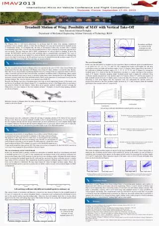
Treadmill Motion of Wing: Possibility of MAV with Vertical Take-Off Iman Samani and Ahmad Sedaghat Department of Mechanical Engineering, Isfahan University of Technology, IRAN Abstract The Magnus effect is well known phenomena for producing high lift values from spinning symmetrical geometries such as cylinders, spheres, or disks. But, the Magnus force may also be produced by treadmill motion of aerodynamic bodies. To accomplish this, the skin of aerodynamic bodies may circulate with a constant circumferential speed. Here, a novel wing with treadmill motion of skin is introduced which may generate lift at zero air speeds. The new wing may lead to MAV configurations for vertical takeoff or landing. To prove the concept, the NACA0015 aerofoil section with circulating skin is computationally investigated. Two cases of stationary air and moving air are studied. It is observed that lift can be generated in stationary air although drag force is also high. For moving air, the lift and drag forces may be adopted between the incidence angles 20 to 25 degrees where lift can posses high values and drag can remain moderate. Streamlines and Mach no. contours for the stationary air with treadmill speed of 1.0 The case of forward flight Background Introduction and Literature Review In this case, the NACA0015 is circulates in a low speed flow. Based on different speed of treadmill motion to air speed (0.2, 0.5, 1.0, 2.0, 3.0, and 5.0), the computational results reveal higher lift and drag coefficients at even very high stall incidence angles of up to 35 degrees. Below figure shows the results of lift coefficient at different incidence angles of 0, 5, 10, 15, 20, 25, 30, and 35 degrees by varying the treadmill speed. It is observed that the lift distribution converges to a nearly envelope at the incidence angle of 25 degrees. Generally speaking, higher treadmill speeds leads to higher lift coefficient. Drag coefficient remains marginal up to the incident angle of 15 degrees (below 0.1) and become negative at high treadmill speeds; however, for higher angle of attack the drag force become considerable. It is also interesting to note from Figures that the separation zone size underneath the aerofoil surface is progressively reduced as the flow incidence angles increases by 0, 5, and 10 degrees while the treadmill speed kept to the constant value of 3; respectively. The first successful device based on Magnus effect was reported in the year of 1924, when Anton Flettner has manufactured the first ship operating with Magnus force using two large cylinders to propel his ship, Buckau. Since that success, the potential of producing high lift forces by rotating bodies in comparison with low lift force values of aerofoil type devices have attracted many researchers in different fields of Engineering. Many patents have been registered in the areas of naval or aerospace applications where claimed the use of the Magnus effect and many research results have been published merely based on the generation of aerodynamic forces from the rotating cylinders. But, very few devices were operated successfully [1]. Recently, the Flettner type rotor is becoming again a hot topic in naval engineering because of the energy costs and the rise of problems with climate change [1]. A comprehensive review of the Magnus effect in aeronautics was given by Seifert [1] who believes “today, there are no specific methods available on how to design the lifting device of a rotor airplane or the rotor airplane airframe.” Examples of aircraft using spinning cylinders are shown in Figures. Different concepts of Magnus effect by using spinning cylinders in the leading or trailing edges of wing were studied as shown in Figure. Lift and drag coefficient with different treadmill speeds in moving air Streamlines and pressure contours for the moving air at zero angle of attack and the treadmill speed of 3.0 Many research were also conducted to obtain lift and drag of spinning cylinders [3-9]. Seifert [1] has stressed that up to now, there are no specific methods available on how to design the lifting device of a rotor airplane or the rotor airplane airframe and new design methods that can show performance of a rotor airplane during flight are required. Moreover, he insists that the negative Magnus force or gyroscopic effects in the case of especially micro aerial vehicles must be considered because their flights occur at low Reynolds numbers. Streamlines and pressure contours for the moving air at angle of attack of 5 degrees and the treadmill speed of 3.0 Text In this paper, the possibility of using Magnus force in Micro Aerial Vehicles using a circulating fixed wing is investigated. A schematic of the wing is shown in Figure. The purposes of this study were two folds. First, we investigated if the circulating wing generates higher lift than non-circulating wing. Second, we investigated if a vertical takeoff is possible at zero air speeds. For these purposes, a fluid flow solver based on high-resolution TVD schemes was used to solve the RANS equations in a Streamlines and pressure contours for the moving air at angle of attack of 10 degrees and the treadmill speed of 3.0 C-type mesh around the wing sections [10]. The wing cross section is assumed to be the NACA0015 aerofoil as a test case to be examined for the possibility of the new targets. The results for higher incidence angles are shown for the lower treadmill speed of 1.0 due to practicality of employing the circulating aerofoil surface with available DC motors in the market. As seen in Figures a separation zone is progressively appears on the upper aerofoil surface by increasing the incidence angles of 15 and 35; respectively. These separation region is the major cause on lower lift gain and higher drag forces as observed in the last Figures. The case of stationary air for vertical takeoff In this case, the NACA0015 is merely circulates in a motionless air medium. Based on a non-dimensional speed of treadmill motion of 0.2, 0.5, and 1.0, the computational convergence results of lift and drag coefficients are shown in the Figure after 10000 iterations for the aerofoil at zero incidence angles. Although the results indicate that by increasing the treadmill speed the lift coefficient has increased, the drag coefficients possess a similar large value of 0.62 at all speeds. The computations should be repeated at different angles of attack to see if this force can be reduced or eliminated. We may expect larger lift values for higher incidence angles. Hence, the proposed treadmill motion is proved to produce lift for further studies towards vertical takeoff flights for MAV configurations. Streamlines and Mach no. contours for the moving air at constant treadmill speed of 1.0 with the angle of attack of 15 degrees Streamlines and Mach no. contours for the moving air at constant treadmill speed of 1.0 with the angle of attack of 35 degrees Concluding remarks The subject of using Magnus force from rotating bodies is fascinating many engineers and scientists to design innovative devices in aerospace and naval engineering. There is a renew interest in Flettner type ships in naval engineering due to increasing trends of fossil fuel costs and climate change concerns. This paper is particularly concerns with a novel fixed wing with treadmill motion to assess possibility of vertical takeoff and landing. The computational results for NACA0015 aerofoil reveals that it is possible to obtain lift from the circulating wing in stationary air. Moreover, the results indicate that it is possible to optimise lift to drag ratios by varying incidence angles. Further work is under progress to find an optimum treadmill wing for a vertical takeoff / landing MAV and for cruise speeds. Lift and drag coefficient with different treadmill speeds in stationary air The contour results of streamlines and Mach no. contours are also shown in Figures for the treadmill speeds of 0.2 and 1.0; respectively. As seen in streamline figures, a separation zone is progressively developing in lower part of the aerofoil surface near the trailing edge. Moreover, the tick boundary layer due to viscous effects appears from the wake and trailing edge region. This further develops by increasing the treadmill speed towards larger zone extending towards the leading edge. Result Reference • [1] Seifert, J., A review of the Magnus effect in aeronautics. Progress in Aerospace Sciences (2012); 55:17–45. • [2] Reid EG. Tests of rotating cylinders. Flight; 1925. • [3] Glauert, M.B., A boundary layer theorem, with applications to rotating cylinders. J. Fluid Mech.; 1957:2:89. • [4] Ingham, D.B., Steady flow past a rotating cylinder. Computers & Fluids; 1983:II(4):351-366. • [5] Mittal, S., Kumar, B., Flow past a rotating cylinder. Journal of Fluid Mechanics; 2003:476:303-334. • [6] Tokumaru, P., Dimotakis, P., Rotary oscillation control of a cylinder wake. J. Fluid mech.; 1991:224:77-90. • [7] Badalamenti, C., Prince, S.A., The effects of endplates on a rotating cylinder in cross flow. AIAA; 2008:7063. • [8] Thouault, N., Breitsamter, C., Seifert, J., Badalamenti, C., Prince, S.A., Adams, N.A., Numerical analysis of a rotating cylinder with spanwise discs. 27th International Congress of the aeronautical Sciences, ICAS; 2010. • [9] Labrag, L., Bouraba, N., Berkah, T., Wall shears stress from a rotating cylinder in cross flow using the electrochemical technique. Experiments in Fluids; 2002:33:488–496. • [10] Sedaghat, A., Shahpar, S., Comparative Study of High-Resolution Shock-Capturing TVD Schemes, Iranian Journal of Science & Technology, 22 (1), 1998. Streamlines and Mach no. contours for the stationary air with treadmill speed of 0.2